Unless they are too slow the rising and falling time of the clock don't affect the digital to analog conversion.
As I already said what really matters is the fluctuation of the time interval between the edges, which creates the jitter.
Unfortunately the beauty of the wave form does not improve jitter.
Andrea
Hi Andrea,
I’m sorry but I really can not agree on that.
Slower clock edges will result in more jitter which is a well known principle.
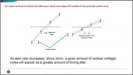
The first picture shows that principle. Basically vertical noise (AM noise, such as power supply noise, EMI noise and so on) can be modulated into jitter ( PM or FM noise). Because the threshold window time is wider, for a given amount of vertical noise, slower clock edges will result in more modulated jitter. And all this kind of additive jitter is more likely to be close-in phase noise because the additive jitter is mainly in decades of fs range corresponding to the original clock signal.
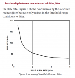
The second picture shows the relationship between clock signal slew rate and additive jitter. You can see higher slew rate (faster rising/falling edges) generates less additive jitter.
Rather than the clock side, this issue most likely happens at the receiver side such as a DAC.The time domain measurement equipment will see the same case, for example a high speed digital scope.
But I have never seen this kind of additive phase noise shown in your Timepod phase domain measurement results. Maybe you should think of why this kind of issue can not be detected in your measurement. This also explains why you even worry about the mechanical vibration but choose to ignore the time domain clock signal quality.

SlewRateVsJitter by Ian, on Flickr

SlewRateJitterRelationship by Ian, on Flickr
Regards,
Ian
Attachments
Last edited:
Anyone wondering if supplying dedicated power to J4 on ReclockPi is worth the effort? It is.
Quite substantial change in fact. Much like installing ReclockPi over FIFO. Another clock upgrade.
The number of separate power supplies I need has increased exponentially! ReclockPi was a nice upgrade to Fifopi and using it with a Buffpro9038 has helped take some of the high-end sharpness off and added a more full sound.
Rise time
@ Ian,
Thanks for interesting post on the slew rate jitter.
My thoughts:
1. So we need to compare the slew rate at the switching point. In your post where you measured the fall / rise time, this is probably done by your scope software and is likely taking a larger window to measure. Could you zoom in that measurement and read yourself what the real slew rate line at the switch “point” is? Then we know the real meaningful value
2. I also noted that your probes are 1:1 - Unless you have super wicket probes, for high speed signals you normally do (or at least I do) is using 1:10 probes for their much higher bandwidth. No offense, just asking/clarifying/checking....
3. This concept can be mathematically correlated it seems. If your noise is let’s say 1mV and the slew rate 1V/ns the uncertainty window round switching would be t=V / (Slew-Rate) = 1mV / (1/(1V/ns)) = 1ps…
4. now is that good or bad? Probably depending on the frequency of the noise modulation I would say. Low frequency noise will create also close-in phase noise I think. Looking at the close-in phase noise from the 5-6MHz clock from Andrea the phase noise correlates to roughly 10fs- so we should stay below this – Meaning 10fs = Noise (V) / (Slew Rate). Take the 1ns rise time (slew rate = 1GV/s) again your maximum noise would be 10uV round the switching point. This would be a signal/noise ratio (of the complete digital signal = Vcc) of -110dB. That is quite a number….
5. Ok, let’s continue, so if we could reduce low frequency noise in the digital signal, the Jitter would be less prone to spoil the music signal? Interestingly, this is exactly what Yuri Kharlamov described in his experiments with the DDDAC. He observed that this was the most important topic to look at (Low frequency noise)
6. Guido Tent explained in one of his white papers why it would be beneficial to decouple digital signals between source and receiver (like I do in the DDDAC with 22 Ohm resistors at the DAC I2S input). Let’s assume the input capacitance is 10pF. Now the slew rate limitation for a 3,3V digital signal, (assuming the gate driving this can deliver the needed current) would be roughly 5GV/s for 1 volt or equivalent risetime of 0,2 ns (1V). As the source is never zero this will probably be more like 0,5 to 1 ns.
7. It all comes close to these numbers looking at practical examples and observations – does that mean there is room for small tweaks? as they come to mind:
a. Make sure the driver gate can deliver really high current and is high speed (Like the re-clock pi ??)
b. Reduce noise further on the clock line and input by having a not too large decoupling resistors (should not limit slew rate too much) and also reduce noise to the max directly at the sending and receiving chip (DAC chip) with shunt regulators or ultra-caps (close to the chip, not too far away….)
Looking at what we all do instinctively as DIY on our DACs, there seems to be correlation to other theories and measurements which is very nice. I hope I am not getting too enthusiastic about this as I maybe just want to believe this, LOL
I did not completely think this through till the very end what it means and what would matter or even better what would be a solution, but may be some one can shoot holes in this or can contemplate further on this?
Last edited:
Hi Ian,
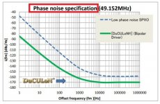
so do you think a lot of engineers at Nihon Dempa Kogyo Co., Ltd. (or NDK), one of the world's largest quartz crystal companies, who have designed the DuCuLon oscillator specifically for audio, don't know the effect of rising/falling edges of the clock on jitter?
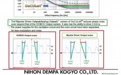
By your reasoning, if you look at both HCMOS and Bipolar Driver output wave, the DuCULoN OCXO it's a poor device because its rising and falling edges are slow to very slow.
Although it was designed specifically for audio use.
Jitter is dominated by the close in phase noise and not by the noise floor.
This is clearly demonstrated by the plots I have published in post #6616
Asynchronous I2S FIFO project, an ultimate weapon to fight the jitter
Every time you move the integration bandwidth to higher frequencies (far from the carrier) the jitter improves.
When the integration bandwidth is 1Hz-100kHz, the RMS jitter of the Crystek is 2.4ps.
Moving the integration bandwidth to 1KHz-100kHz the RMS jitter of the Crystek becomes 27fs, almost 100 times better (40 dB)!
It would be simple but it's not so.
The problem is that with your digital oscilloscope you are substantially measuring the noise floor rather the close in noise.
You cannot measure the noise at 10 Hz from the carrier and below because likely the time base of your digital oscilloscope is worse than the DUT in this region.
And the software does not help because you would need cross correlation (hardware and software) to overcome the limits of the time base used to sample the signal.
So in the end you lose the noise contribution that weighs more on the jitter, which is the close in noise and not the noise floor.
Andrea
so do you think a lot of engineers at Nihon Dempa Kogyo Co., Ltd. (or NDK), one of the world's largest quartz crystal companies, who have designed the DuCuLon oscillator specifically for audio, don't know the effect of rising/falling edges of the clock on jitter?
By your reasoning, if you look at both HCMOS and Bipolar Driver output wave, the DuCULoN OCXO it's a poor device because its rising and falling edges are slow to very slow.
Although it was designed specifically for audio use.
Jitter is dominated by the close in phase noise and not by the noise floor.
This is clearly demonstrated by the plots I have published in post #6616
Asynchronous I2S FIFO project, an ultimate weapon to fight the jitter
Every time you move the integration bandwidth to higher frequencies (far from the carrier) the jitter improves.
When the integration bandwidth is 1Hz-100kHz, the RMS jitter of the Crystek is 2.4ps.
Moving the integration bandwidth to 1KHz-100kHz the RMS jitter of the Crystek becomes 27fs, almost 100 times better (40 dB)!
It would be simple but it's not so.
The problem is that with your digital oscilloscope you are substantially measuring the noise floor rather the close in noise.
You cannot measure the noise at 10 Hz from the carrier and below because likely the time base of your digital oscilloscope is worse than the DUT in this region.
And the software does not help because you would need cross correlation (hardware and software) to overcome the limits of the time base used to sample the signal.
So in the end you lose the noise contribution that weighs more on the jitter, which is the close in noise and not the noise floor.
Andrea
Attachments
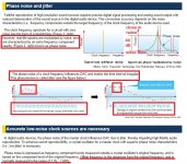
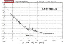
Please, take a look at the attached picture.
"The phase noise of a clock frequency makes the time interval irregular.
This phenomenon is called jitter".
As you can see at the top-right of the picture the phase noise is far higher close to the carrier.
It's this noise that makes the time interval irregular causing jitter.
The noise floor doesn't matter much because its level is usually far lower than the close in noise , 40 dB and more.
Finally, "Offset frequency is the departure from the original frequency, and is normally measured in the range of 1 Hz - 1 MHz.", that's exactly the measurement performed using a phase noise analyzer tool.
The result is the spectrum of the noise, necessary to identify the components of noise itself.
While the jitter measured as a standalone number does not say anything about the spectrum of the noise, and it's heavily influenced by the arbitrary integration bandwidth chosen for the measurement.
Attachments
Slower clock edges will result in more jitter which is a well known principle.
Agreed that it is a well-known effect. However, that model neglects other possible coexistent effects which may be improved by somewhat reduced slew rate. The composite effects may vary according specifics of dac design and PCB layout. Thus, it may be possible to search the sound reproduction variable space for optimal slew rate on a case by case basis. This has been known for many years, at least by some dac designers.
...DuCULoN OCXO it's a poor device because its rising and falling edges are slow to very slow.
Although it was designed specifically for audio use.
That the clocks were designed for audio may seem apparent from the frequencies in which they are offered. However, direct communications with NDK about it resulted in a statement from NDK that DuCULoN clocks are intended solely for use in satellites.
Last edited:
Mark I think your point is well demonstrated in the extensive optimization of the TDA1541a. Two methods of reducing self induced jitter are 1. the use of synchronous PCM signal, and 2. attenuation of the input signals. ecdesigns proposed two schemes for the latter, and Ryanj experimented with both determining both to be an improvement but one clearly superior in his implementation of the chip.
Hi Mark,
they use an oven so the DuCULoN oscillators were designed in the same way they design for satellite applications (short and long term stability), but the datasheet is clear: Oven controlled “Dual Crystal Ultra Low Noise” oscillator
for master clocks in digital high-end audio products.
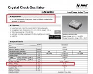
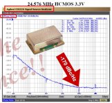
Please, take a look at the NDK NZ2520SD oscillator datasheet, designed for High-quality Audio.
The rising/falling time is specified as 6ns, much more than the one of the AC04 sine to square converter.
But it looks like it's more appreciated by audiophiles than the Crystek.
they use an oven so the DuCULoN oscillators were designed in the same way they design for satellite applications (short and long term stability), but the datasheet is clear: Oven controlled “Dual Crystal Ultra Low Noise” oscillator
for master clocks in digital high-end audio products.
Please, take a look at the NDK NZ2520SD oscillator datasheet, designed for High-quality Audio.
The rising/falling time is specified as 6ns, much more than the one of the AC04 sine to square converter.
But it looks like it's more appreciated by audiophiles than the Crystek.
Attachments

Basically vertical noise (AM noise, such as power supply noise, EMI noise and so on) can be modulated into jitter ( PM or FM noise). Because the threshold window time is wider, for a given amount of vertical noise, slower clock edges will result in more modulated jitter. And all this kind of additive jitter is more likely to be close-in phase noise because the additive jitter is mainly in decades of fs range corresponding to the original clock signal.
Hi Ian,
your reasoning makes sense, but i'm sorry to say you have drawn wrong conclusions.
This kind of additive jitter affects the noise floor only and not the close-in phase noise.
Exactly the opposite of your conclusions.
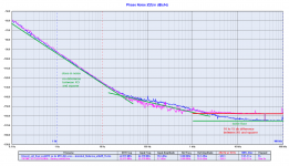
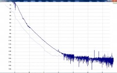
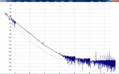
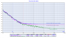
Please, take a look at the attached plots, they show the comparison between the measured phase noise of the Driscoll oscillators at 5 and 22 MHz in respect to the measured phase noise of the same oscillators followed by the AC04 sine to square converter.
As you can see the close-in phase noise is exactly the same, while the noise floor increases.
Even with the 5.6448 MHz DRIXO oscillator (which has a spectacular close in phase noise) the close in phase noise after the squarer is the same of the sine wave oscillator, around -150dBc at 10 Hz from the carrier.
This means that the additive jitter you are pointing out does not affect the close-in phase noise at all.
Moreover your digital oscilloscope is not able to measure such phase noise (at 10 Hz or lower from the carrier), or such low jitter if you want (fs).
Andrea
Attachments
Last edited:
...it looks like it's more appreciated by audiophiles than the Crystek.
Could be NDK SDA is easier to get sounding good as verses the case with Crystek. With proper care and feeding I find Crystek to give better SQ for my dacs. That includes some 'selected' NDA SDA I got from Jocko.
Regarding DuCULoN, the data sheet does mention high end audio, but a friend knows the NDK rep in this part of the world. We put in a request through rep to possibly sample or test DuCULoN for high end audio dac use. The satellite story is what the rep came back with after checking with the factory. He also said the clocks cost around $2,000 each.
Thanks Ian, for continued investigation on how to get the best clock solution for the FiFoPi. Looking forward to your ideas and observations.
In the meantime, I got my Accusilicon 338 series. I will do testing soon after they are a few days on power….
To make sure, when comparing clocks, all clocks are „warm“, I needed to make a small solution. See the pics…. It is like a clock warm keeper and the Bluetooth selector will enable real A_B switching from the listening position (smartphone app controls the 4 relays) - so 4 clocks can be compared all at once without any clock being unpowered ….
I am using your UC-conditioner and linear pi for the testing….
Will report back my view of things
I just posted about this on my blog site:
ANDREA's CLOCK - part 2 - DDDAC
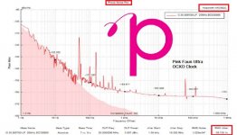
It is interesting to note that the unobtainable $2k DUCALON is -120dBc vs WTMC 5MHz -150dBc at 10 Hz from the carrier.
And let's not loose site of the fact that the vast majority of us using WTMC with its squarer are enjoying a substantial improvement in sound quality over Crystek and NDK. I recently installed the 48MHz NDK SDA and compared it to the 5MHz WTMC. Same track, one at 96kHz the other at 44kHz. Same DAC, same system. One high end the other run of the mill. No contest.
Actually quite remarkable how much quality was there in the electronics and speakers that I'd never realize without the source upgrade.
Ian,
I'm sorry to repeat myself, but your digital oscilloscope is not enough accurate to measure the close in phase noise (and so the jitter) of real low noise oscillators.
Please, take a look at the attached plots, they represent the way in which the major manufacturers characterize their oscillators for audio use, all are square wave output.
Why do you think they all have used a Phase Noise Analyzer tool rather than a digital oscilloscope?
They would have saved a lot of money, but they didn't.
The reason is simple, a digital oscilloscope is suitable to measure the jitter of oscillators designed for telecommunication, using an integration bandwidth suitable for such applications (such 12kHz to some MHz), but not to measure low phase noise oscillators.
Your LC584AXL 1GHz Oscilloscope with jitter measurement package has the same jitter of the Crystek CCHD-957 or maybe worse.
And the Crystek CCHD-957 is not certainly a low phase noise oscillator.
Please take note and buy a suitable tool like a Phase noise analyzer to make such measurements.
Attachments
Hi Ian,
your reasoning makes sense, but i'm sorry to say you have drawn wrong conclusions.
This kind of additive jitter affects the noise floor only and not the close-in phase noise.
Exactly the opposite of your conclusions.
Please, take a look at the attached plots, they show the comparison between the measured phase noise of the Driscoll oscillators at 5 and 22 MHz in respect to the measured phase noise of the same oscillators followed by the AC04 sine to square converter.
As you can see the close-in phase noise is exactly the same, while the noise floor increases.
Even with the 5.6448 MHz DRIXO oscillator (which has a spectacular close in phase noise) the close in phase noise after the squarer is the same of the sine wave oscillator, around -150dBc at 10 Hz from the carrier.
This means that the additive jitter you are pointing out does not affect the close-in phase noise at all.
Moreover your digital oscilloscope is not able to measure such phase noise (at 10 Hz or lower from the carrier), or such low jitter if you want (fs).
Andrea
Hi Andrea,
Actually your Timepod can not see the additive phase noise of the sine to square wave converter, because Timepod converts the square wave into sine wave by a LPF before make the measurement.
That's why you got similar close-in phase noise results after the STS. However what you see the increment on the phase noise plot noise floor could be the leakage of high frequency square wave harmonic components from that LPF.
Regards,
Ian
Hi Ian,
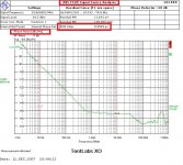
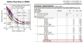
please take a look at the following plot extracted from the datasheet of the LTC6957.
They used an Agilent E5505, which is a Phase Noise Measurement System, to measure the additive jitter of the LTC6957, and not a digital oscilloscope.
The Timepod measure phase noise and jitter in the same way of the Agilent E5052 and the RS FSWP, with 4 ADCs and cross correlation software.
Your digital oscilloscope cannot measure 90 or 142 fs of additive jitter, ther is no way, please take note.
Without the spectrum of the noise your assumptions are just assumptions, since your jitter measurement (although wthout an accurate tool) does not provide the spectrum of the noise.
Andrea
Attachments
This is a Crystek CCHD 957 45,184MHz unit.. It looks a bit better than on the datasheet
Without DIL socket and powersupply filtered for both crystal by a close 1 uF FCPA Cornel Dublier smd, it sounds nice: I did that 6 years ago. It improves things a lot in synergy of the caps seen inside the Crysteck metal casing...
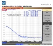
In the end, I would like to point out that the choice of the AC04 picogate was not accidental.
In the RF circuit is well know that the AC04 is one of the best device to convert sine into square wave signals, better than a comparator and even better than an ECL device.
The choice is due to the multiple measurements we made.
In fact, following the measurements we found that the AC04 is an excellent device to do the job.
We also have given a try to the modern LTC6974, which is a very expensive device.
It's the device we have used in the TWTMC-FSDO board.
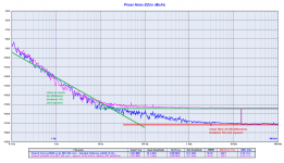
I attach the phase noise plot comparison between the LTC6957 and the AC04 sine to square converters.
As you can see there is not much difference, the close in phase noise is the same and it's even the same of the sine wave oscillator at 5.6448 MHz.
While the noise floor of the LTC6957 is a little worse in respect to the AC04, just a few dB.
BTW, we are also working on a no-compromise sine to square converter to be used in our top audio system, but it will be much more complex and expensive.
And the only goal will be to get the same noise floor of the sine wave oscillator, since there is no way to improve the close in phase noise to get it better than the sine wave oscillator.
Ian,
anyway if you build your own sine to square converter we will be happy to try it in our audio system.
In the RF circuit is well know that the AC04 is one of the best device to convert sine into square wave signals, better than a comparator and even better than an ECL device.
The choice is due to the multiple measurements we made.
In fact, following the measurements we found that the AC04 is an excellent device to do the job.
We also have given a try to the modern LTC6974, which is a very expensive device.
It's the device we have used in the TWTMC-FSDO board.
I attach the phase noise plot comparison between the LTC6957 and the AC04 sine to square converters.
As you can see there is not much difference, the close in phase noise is the same and it's even the same of the sine wave oscillator at 5.6448 MHz.
While the noise floor of the LTC6957 is a little worse in respect to the AC04, just a few dB.
BTW, we are also working on a no-compromise sine to square converter to be used in our top audio system, but it will be much more complex and expensive.
And the only goal will be to get the same noise floor of the sine wave oscillator, since there is no way to improve the close in phase noise to get it better than the sine wave oscillator.
Ian,
anyway if you build your own sine to square converter we will be happy to try it in our audio system.
Attachments
- Home
- Source & Line
- Digital Line Level
- Asynchronous I2S FIFO project, an ultimate weapon to fight the jitter