The
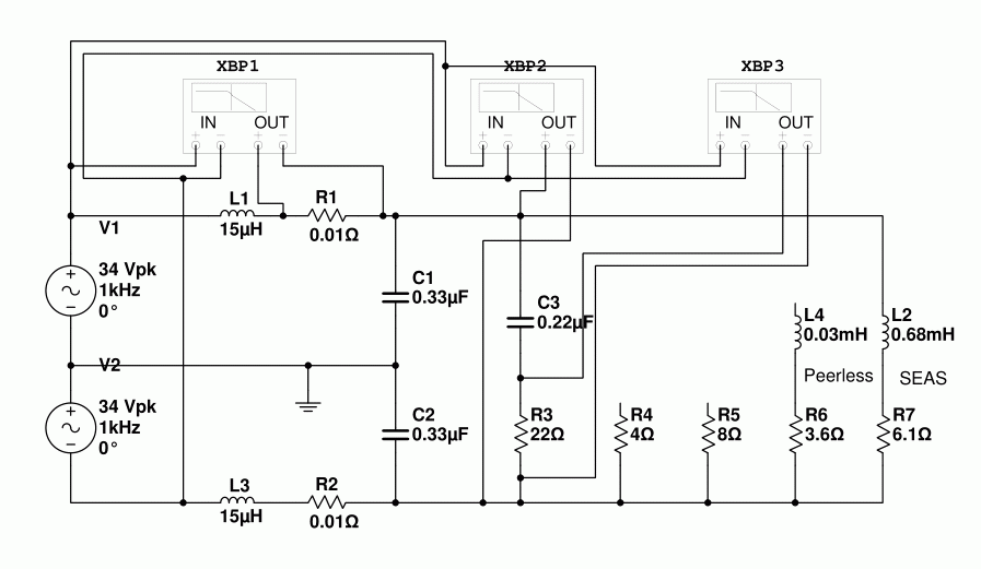
I also use an educational programming called YENKA. Its just as easy to construct circuits, and the best part is the Graph measurement tool.
The graph has 4 points it can show. So you can join each part to different component, or to different circuit traces, or to a combination. Can also show current or voltage etc, but must be same at all 4 points at same time.
I like the graph ability of the programming as you can set the input of the circuit as a signal generator and then see it on the graph in action through relevant component. Brilliant for visualising comparison of the delay of signal through crossover channels.
A note about Yenka. It does have a time limited use period on the free home version of only using out of "school working hours". To get around this just adjust your computer clock to after 3pm if going to use it before 3pm. Apart from that its a free years license which you can renew for free at end of year.
Another great package is Texas Instrument's TINA. A free SPICE program with built in library of TI parts.
Give it a try...
I also use an educational programming called YENKA. Its just as easy to construct circuits, and the best part is the Graph measurement tool.
The graph has 4 points it can show. So you can join each part to different component, or to different circuit traces, or to a combination. Can also show current or voltage etc, but must be same at all 4 points at same time.
I like the graph ability of the programming as you can set the input of the circuit as a signal generator and then see it on the graph in action through relevant component. Brilliant for visualising comparison of the delay of signal through crossover channels.
A note about Yenka. It does have a time limited use period on the free home version of only using out of "school working hours". To get around this just adjust your computer clock to after 3pm if going to use it before 3pm. Apart from that its a free years license which you can renew for free at end of year.
Probably stupid question, is LTSpice limited to one source? I mean I keep seeing the SE filtersims. Or is there a reason that sim works better? Me being lazy I downloaded TrevorMarshall sim and changed the ouputcomponents, but maybe that setup isn't good? It at least allows Re/Le speakervalues without conversion and if you want probably advanced electrical parameters like schematic in Scanpeak datasheet, if you want more accurate speaker model? Seemed easiest to me.


Just a thought. This is a DIY forum, so maybe we should not go overboard and do overly complex circuit simulations.
After all, to get really precise you'd have to make a rather complex circuit.
For example each single capacitor should be replaced by an equivalent circuit such as this
The same goes for every single other component. The PCB itself will also have a rather complex equivalent circuit. Cables too. Inductors have saturation graphs that must be taken into account. Ceramic capacitors have voltage droop and so on.
Simulating on a realistic load defined as RE and LE of a driver would for the vast majority of DIYer be more than enough accuracy.
After all, to get really precise you'd have to make a rather complex circuit.
For example each single capacitor should be replaced by an equivalent circuit such as this
An externally hosted image should be here but it was not working when we last tested it.
The same goes for every single other component. The PCB itself will also have a rather complex equivalent circuit. Cables too. Inductors have saturation graphs that must be taken into account. Ceramic capacitors have voltage droop and so on.
Simulating on a realistic load defined as RE and LE of a driver would for the vast majority of DIYer be more than enough accuracy.
(posting this again as it did appear and then disappeared)
Keeping it reasonably simple, below is the tlspice graph of the 15uh/0.47uf lc filter as posted earlier by gmarsh. EXCEPT, for this result the emi snubber from the 3116 datasheets was added, and the "snubber mod" from the EVM was added.
Question..... is the 0degrees on the voltage supposed to be at +5db? Or is it supposed to be 0db. Also notice the slightly different angles at the top end of frequency at 180degrees.

At a glance it doesn't look quite as good. The originally posted circuit had the exact -40dB at Fcx10. With the inductor snubber (aka bootstrap snubber) this seems to have dropped to -37-38dB. So at least in theory and in simulation it should perform worse but we know that this is not the case in practical application.
At a glance it doesn't look quite as good. The originally posted circuit had the exact -40dB at Fcx10. With the inductor snubber (aka bootstrap snubber) this seems to have dropped to -37-38dB. So at least in theory and in simulation it should perform worse but we know that this is not the case in practical application.
Itss not the "bootstrap snubber" that changes it Saturnus, Its the EMI snubber cap values. I've used this, and various other lc filter coil/cap values and been able to get the phase at either 0db or less @ 0degrees, and have the phase line up perfectly at 180degrees by using a different formula to work out emi snubber.
WITHOUT changing the "bootstrap snubber" values from evm.
I read during some research on phase angle in relation to human hearing and sound location that there is considered a "magic value" of 38 degrees for the human ability of separating sound locations..... Maybe that has something to do with it!
I suppose it would, as anyone changing lc filter will have this if the emi circuit values aren't corrected whether they do the bootstrap mod or not!
Mguntrum,
...It looks like the tsop 32 breakout board worked very well for your needs...

Hi - I was hoping you could steer me onto the source for these. I've been looking for a part - but it seems a bit steep. At this rate I could just make my own protoboard for $10
Thanks in advance!
If you want to use a resistorvalue I would use 30ohm (15ohm SE) for that 8ohm woofer (measured average inductance (72khz) 3 of my "loose" 8 ohm woofers converted to impedance, dc vc resistance added gives around 30 ohm)
(btw small some will say tweeter sized woofers, vifa tc9 among them)
(btw small some will say tweeter sized woofers, vifa tc9 among them)
Last edited:
I'll give the 30ohm a go. Unfortunately budget doesn't run to much, so testing equipment not something I am privy to.
I have been putting a 350uh inductor in series with the 4ohm resistor in tlspice, as suggested in an Elliott sounds article.
I have been putting a 350uh inductor in series with the 4ohm resistor in tlspice, as suggested in an Elliott sounds article.
Hi - I was hoping you could steer me onto the source for these. I've been looking for a part - but it seems a bit steep. At this rate I could just make my own protoboard for $10
Thanks in advance!
The link in post #6
TSSOP to DIP adapter 32-pin 0.65mm pitch
$2 is cheap in my book. Especially for the headache it saves compared to me soldering the chips via hand held wirebonding in dead bug style.
If you want to use a resistorvalue I would use 30ohm (15ohm SE) for that 8ohm woofer (measured average inductance (72khz) 3 of my "loose" 8 ohm woofers converted to impedance, dc vc resistance added gives around 30 ohm)
(btw small some will say tweeter sized woofers, vifa tc9 among them)
WoW.. You a star.. I set up 3 identical spice circuits, then left 1 with the 4ohm resistor, changed 1 to a 4ohm resistor with 350uh inductor in series, and 1 to suggested 15ohm resistor.
I then recalculated the emi snubber circuit for the 15ohm resistor circuit. When I used the recalculated values of the 15ohm load emi snubber in all 3 of the circuits....Eureka!
Amazingly the values transform voltage and phase lines. Of course, that's using equations I have manipulated from others intended uses!!
Very happy, cheers me up after the 100nf PP caps I got in post today were way to big for intended location.
I have some interest in the TPA-3116.
Has anyone tried the Sure TPA-3116 monoblocks?
How do they compare to the normal 2 channel amps?
Sure Electronics' webstore 1 X 100Watt Class D Audio Amplifier Board -TPA3116
Has anyone tried the Sure TPA-3116 monoblocks?
How do they compare to the normal 2 channel amps?
Sure Electronics' webstore 1 X 100Watt Class D Audio Amplifier Board -TPA3116
If you haven't tried another 3116 ampboard try the stereo btl version, 3 ohm isn't a big problem for stereo board. If you know your speakers drop even lower, impedance, then mono boards would be better choice for certain.
This response looks good. But if you assume there is 1-4mH inductance on the speaker loading in series with 4 Ohm, you can observe a peaking after 20kHz, maybe up to 20dB higher. But this assumption may not be right, I do not have a good model of a decent 2-way or 3-way speaker. But if there is any inductance on the speaker, you will see peaking in general. So it will depends on the speaker, you might not get a flat response at high frequency.
My silly mistake this morning in adding the snubber to the circuit. Here is the same circuits with the load value halved.
View attachment 481022
This response looks good. But if you assume there is 1-4mH inductance on the speaker loading in series with 4 Ohm, you can observe a peaking after 20kHz, maybe up to 20dB higher. But this assumption may not be right, I do not have a good model of a decent 2-way or 3-way speaker. But if there is any inductance on the speaker, you will see peaking in general. So it will depends on the speaker, you might not get a flat response at high frequency.
You are correct. Following advice I put a 350uh inductor in series with 4ohm resistor (this is a 8ohm driver, not 2 or 3 way).
This does show peaking, and altering the emi snubber values can adjust the peaking in both frequency, and dB. The theory I am using to adjust the emi is as follows:
Choose a value for the single cap in emi snubber, can even leave as is. Now use following equations:
For resistor: Rs= √(Lt÷Cq)
For capacitor in series: Cs= 1÷(2×π×√(Lt×Cq))
Lt: filter inductor
Ct: filter cap
Rs: emi resistor
Cs: emi cap in series
CX: emi cap
Cq=Ct+Cx
Setting up 3 spice circuits(1 with 4ohm resistor, 1 with 4ohm and 350uh coil in series, and 1 with 15ohm resistor) I used the equations and all 3 circuits showed same graphs for same values.
The clue to why the 15uh / 470nf filter values work may lie in the V(n001) in the spice graph. The relevant component in the circuit which affects it is the CX value from equations above i.e the emi snubber single cap to ground.
Last edited:
- Home
- Amplifiers
- Class D
- TPA3116D2 Amp