Do humans hear phase shift for higher frequencies ? On speakers ? Do the speakers have phase shift and is total system phase shift worse with worst phase output filter graphs above ?
More or less, yes to all. But then we're moving into the more contentious realm of psychoacoustics. It is quite obvious that human hearing is quite sensitive to phase shifts especially at higher frequencies as it is the very method the brain uses to locate sounds. Speakers, their tuning and the environment they're playing in naturally also affect both amplitude and phase response alike.
And you do bring up the interesting point I mentioned in a previous post that all these simulations are done on theoretically perfect loads and with theoretically perfect components. As I wrote in an earlier post one should really optimize the amp for the exact speaker it is intended to drive if at all possible.
Last edited:
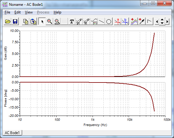
We see about 20 degrees at 10khz, would that be 0.005 milliseconds ? What is smallest step minidsp can adjust, maybe it is easily tried (saw xrk mentioned 0.26 ms delay on SS fullrange in FAST, that suggests 0.01 ms is smallest step, someone could try that on a tweeter, I think it would equal 40 degrees 10khz then?).
Then you'd be missing the point. The realm of psychoacoustics is where we can't blind test and get a cause and effect result but where we can do statistical analysis of listening experiences. The same person can easily have entirely different listening experiences under otherwise identical set ups based on different information given prior to the test for example. That's why it's contentious. Doesn't make it more or less real than double blind tests though.
You're also missing the point that any single contribution, each by themselves undetectable can have a cumulative effect that is. If we have 20 degree phase angle at 10khz in the output filter it might be undetectable in itself but due to most dynamic speakers being inductive there would be a further phase shift in the speaker and these added together could very well be detectable, in some cases even in a blind test.
We have to be careful to rule out causes based on artificial simulations on theoretically perfect components under ideal conditions.
Last edited:
We see about 20 degrees at 10khz, would that be 0.005 milliseconds ? What is smallest step minidsp can adjust, maybe it is easily tried (saw xrk mentioned 0.26 ms delay on SS fullrange in FAST, that suggests 0.01 ms is smallest step, someone could try that on a tweeter, I think it would equal 40 degrees 10khz then?).
Yes, miniDSP has 0.01ms steps. It made a difference in quality of the step response going from 0.26ms to 0.22ms. 0.04ms is 1.4cm of propagation distance and correlates well to resolution needed to time-align multiways.
Yes 0.04ms is getting close, would translate to ~145 degrees phase angle at 10khz? The 0.04ms was clearly audible you would say?
The phase angles canceling or creating additional phase angles between speaker and ampfilter is something that might be detectable in one of your many graphs compared to one of the german magazines, need to have a look if phase is among the graphs, can't remember looking at them")
The phase angles canceling or creating additional phase angles between speaker and ampfilter is something that might be detectable in one of your many graphs compared to one of the german magazines, need to have a look if phase is among the graphs, can't remember looking at them
Yes 0.04ms is getting close, would translate to ~145 degrees phase angle at 10khz? The 0.04ms was clearly audible you would say?
The phase angles canceling or creating additional phase angles between speaker and ampfilter is something that might be detectable in one of your many graphs compared to one of the german magazines, need to have a look if phase is among the graphs, can't remember looking at them
Yes, very audible from standpoint of a coherent and clean percussion backed up with oomph from the woofer. This made the step response measurably better and the sound was very cohesive. It went from good sounding to outstanding sounding.
your 479812 vs 480537 soundclips is what I can compare but difference is more than just 0.04ms, bass is better defined is first noticed improvement and seems better attached/integrated to music, treble also is smoother, both treble and bass closer to original here on headphones. btw the clips are really fun and informative for me, and that speaker is sounding very good and even better in second clip (cliplocations:10F/8424 & RS225-8 FAST Ref Monitor thread)
but difference is more than just 0.04ms, bass is better defined is first noticed improvement and seems better attached/integrated to music, treble also is smoother, both treble and bass closer to original here on headphones. btw the clips are really fun and informative for me, and that speaker is sounding very good and even better in second clip (cliplocations:10F/8424 & RS225-8 FAST Ref Monitor thread)finally the steam has stopped shooting out of both ears!
Much math using many different damping factors to enter into LTspice for comparison...
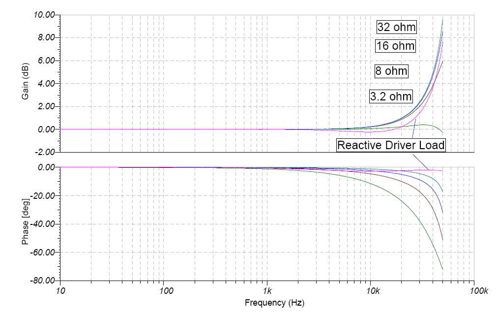
Also,reading about phase affects on amplifiers from various sources online I came across the suggestion (I think by a piece published in audioholics by R.Elliot but dont quote me) to place a 700uh inductor in series with the 8ohm speaker in modelling.
I presumed for the half load that would mean putting a 350uh in series with the 4ohm resistor representing the 8ohm speaker. So this morning I tried it in LTspice... Interesting to see the V and I(load) relationships in the plots at 90degree phase steps.
Much math using many different damping factors to enter into LTspice for comparison...
Also,reading about phase affects on amplifiers from various sources online I came across the suggestion (I think by a piece published in audioholics by R.Elliot but dont quote me) to place a 700uh inductor in series with the 8ohm speaker in modelling.
I presumed for the half load that would mean putting a 350uh in series with the 4ohm resistor representing the 8ohm speaker. So this morning I tried it in LTspice... Interesting to see the V and I(load) relationships in the plots at 90degree phase steps.
Yes, very audible from standpoint of a coherent and clean percussion backed up with oomph from the woofer. This made the step response measurably better and the sound was very cohesive. It went from good sounding to outstanding sounding.
Here are the links to the sound clips in case anyone wants to check it out. The link posted by Irrebeo didn't work. You need to rename the .asc files to .mp3 to listen. These were played from a DUG v1 PCB TPA3116D2 (circa April 2013) amp powered by 19v SMPS laptop brick with 560uF Panasonic FM caps, 3.3uF Panasonic film caps on inputs.
Main thread here: http://www.diyaudio.com/forums/full-range/273524-10f-8424-rs225-8-fast-ref-monitor.html
Sound Clips:
http://www.diyaudio.com/forums/attachments/full-range/480536d1430447820-10f-8424-rs225-8-fast-ref-monitor-10f-8424-rs225-8-fast-bw1-350hz-clip-.asc
http://www.diyaudio.com/forums/attachments/full-range/480537d1430447820-10f-8424-rs225-8-fast-ref-monitor-10f-8424-rs225-8-fast-bw1-350hz-clip-b.asc
http://www.diyaudio.com/forums/attachments/full-range/480538d1430447820-10f-8424-rs225-8-fast-ref-monitor-10f-8424-rs225-8-fast-bw1-350hz-clip-c.asc
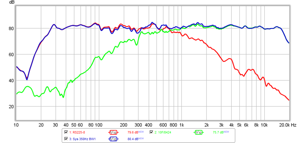
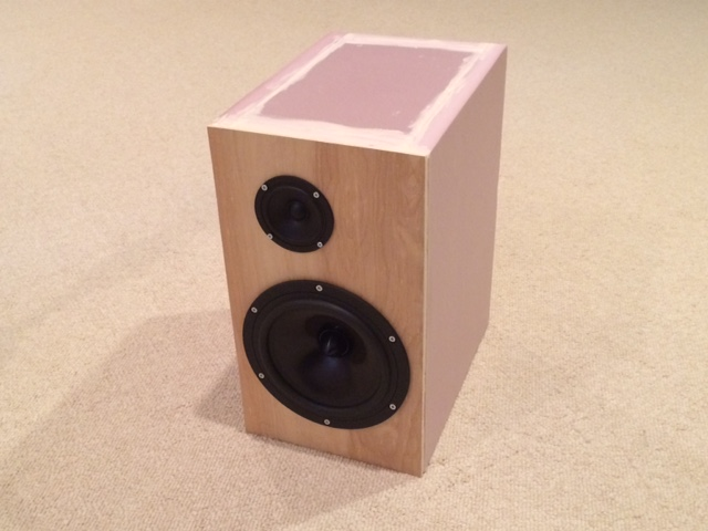
Here are measured specs of the reference monitor made from 1in thick pink XPS foam and ScanSpeak 10F/8424 driver for the top and Dayton RS225-8 driver for the bass. miniDSP serving as XO, no EQ used except for Linkwitz transform on bass.
Measured XO slopes:
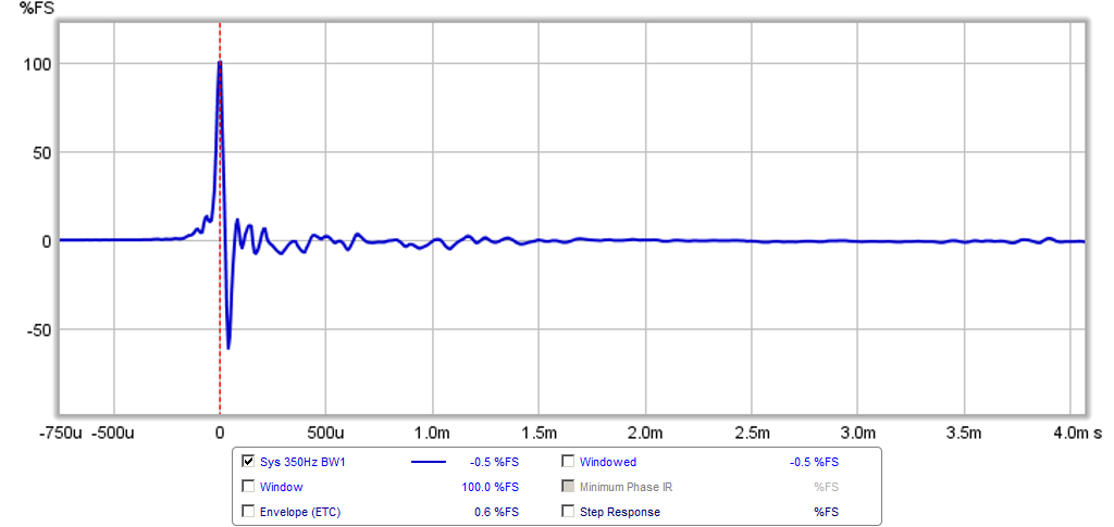
Measured Impulse Response:
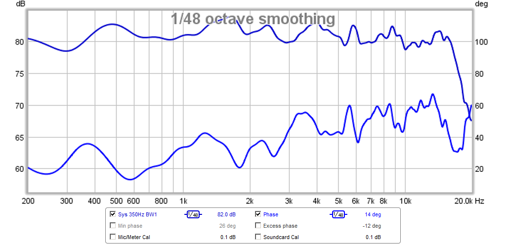
Measured FR and absolute phase with 4ms gate:
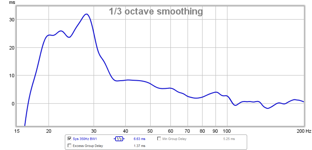
Measured Group Delay:
Measured Step Response:
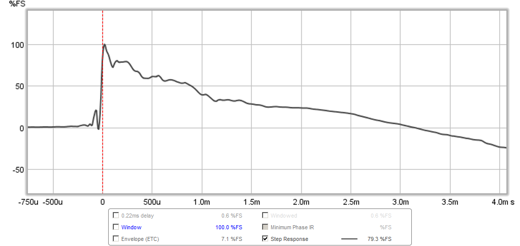
The above plot is actually really special if you are not familiar with how difficult it is to achieve in a speaker. More info on Step Response in this nice article: http://www.stereophile.com/content/measuring-loudspeakers-part-two-page-2
I think I finally have speaker that has enough performance to really be able to test the effects of different amplifers on the sound quality.
Last edited:
Hello X,
Firstly, thanks for all your effort and sharing your results.
I appreciate the the way in which define, execute and finally document your trials. I would think you are carrying over your day job methodology.
Two questions for you.
Are both drivers sharing the same volume or are they separated from each other internally (sorry if you posted before and I missed it)?
When do you find time to sleep?
Andrew
Bootstrap function
I believe the bootstrap cap is used for supply to turn on NMOS inside the IC when the D-class switches its output to +VDD. The gate voltage of the switch need to to be higher than VDD, the bootstrap can provide it. It is not intended to filter output signal. So I would choose smaller SMD caps for these, they will have less fringe capacitance to surroundings, thus less EMI and sharper transition, at least in theory.
I believe the bootstrap cap is used for supply to turn on NMOS inside the IC when the D-class switches its output to +VDD. The gate voltage of the switch need to to be higher than VDD, the bootstrap can provide it. It is not intended to filter output signal. So I would choose smaller SMD caps for these, they will have less fringe capacitance to surroundings, thus less EMI and sharper transition, at least in theory.
As DUG said, the main power cap mod is low ESR is good because it provides a higher transient current ability for bass and sharp transients like percussion.
The bootstrap snubber is simply following TI's evaluation board schematic and helps to remove the high frequency harshness. It makes an audible difference in smoothness and is a very cheap fix.
The larger input caps extend the low frequency cutoff of the amp to a solid 20Hz vs 40Hz (depending on gain setting). Better caps also improve sound quality for highs. There is some debate whether or not tiny 10uF SMT ceramic caps are better because they don't act as antennas and pick up RF like large metal foil polyester caps. I have used both and like both.
I believe the bootstrap cap is used for supply to turn on NMOS inside the IC when the D-class switches its output to +VDD. The gate voltage of the switch need to to be higher than VDD, the bootstrap can provide it. It is not intended to filter output signal. So I would choose smaller SMD caps for these, they will have less fringe capacitance to surroundings, thus less EMI and sharper transition, at least in theory.
We are talking about the "bootstrap snubber" (a name I coined simply because of its proximity to the bootstrap cap, but is in fact, an RC filter (or snubber) connected to the output near the bootstrap cap connection between the bootstrap cap and the output inductor. You are probably right about the bootstrap cap, proper needing to be small SMT for high speed.
Just download a copy of LTspice and do AC sweeps of whatever filter you come up with, eg for 8 ohms:

Would you mind uploading the .asc file here? I'm having trouble figuring out how to build this sim.
Hello X,
Firstly, thanks for all your effort and sharing your results.
I appreciate the the way in which define, execute and finally document your trials. I would think you are carrying over your day job methodology.
Two questions for you.
Are both drivers sharing the same volume or are they separated from each other internally (sorry if you posted before and I missed it)?
When do you find time to sleep?
Andrew
Andrewbee,
Thanks for the kind words.
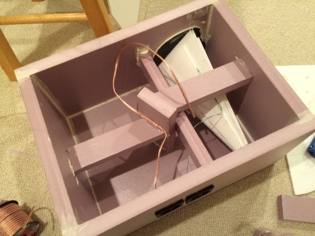
If you look at the thread, it says that the 10F/8424 fullrange utilizes a Dagger TL, which is referring to a 'dagger' shaped 3-side pyramid sealed transmission line that I use as an acoustic 'black hole' on the rear of the driver. It is formed simply by gluing qnty 3 by 12.5in tall x 6 in wide triangles together to form a long dagger like shape. The Dagger is stuffed with fiberglass or polyfill and has almost zero back reflection for a very open, non boxy sound given the volume is only 1.1 liters. The lack of coloration or back reflection can be seen in the measured response being flat within 2dB over its whole operating bandwidth.Here is a photo of the Dagger TL (white pyramid) as built inside this pink XPS foam monitor:
More info on my first use of a Dagger TL:
http://www.diyaudio.com/forums/full-range/268037-fast-tl-8.html#post4192688
If you have more questions, probably best to ask in those threads to keep us on-topic here.
You are right, I don't sleep much...
Thanks for your interest.
Would you mind uploading the .asc file here? I'm having trouble figuring out how to build this sim.
Another great package is Texas Instrument's TINA. A free SPICE program with built in library of TI parts.
SPICE-Based Analog Simulation Program - TINA-TI - TI Software Folder
Here is a similar circuit I made for filter analysis:
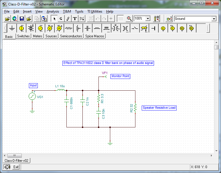
The circuit file is also atached as zip file. Once you install downloaded program, open the file and click on components to change. You can easily remove or add components and re-wire with point and click. Very simple.
Give it a try...
Attachments

Last edited:
Pure resistive speaker?
While a pure resistive load is naturally not ideal for simulations. It'll give a good estimate on where to start doing actual simulations with equivalent circuits for every single component. And that's not just the speakers and speaker cables but also each component in the output filter as well as the outputs inside the chip itself all have to be replaced by actual equivalent circuits for relatively accurate simulations. And even then, it's only a simulation which doesn't take interference artifacts and environmental artifacts into account.
Last edited:
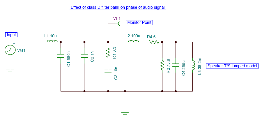
Pure resistive speaker?
That was just an example to get folks started. I added elements corresponding to T/S parameters of a driver in this version and examined the effect of driver reactance on the phase. This was posted somewhere in this thread:
http://www.diyaudio.com/forums/class-d/261231-class-d-output-filter-design.html#post4041590
So
?- Home
- Amplifiers
- Class D
- TPA3116D2 Amp