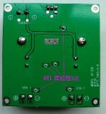
Correct. There are five solder pads. Two of them is at the top side, one is near the inputs, other two is in the middle, but middle ones are for bootstrap mod afaik.
I found this picture from my archive showing the connection. As I said, I did not see that in the picture that you posted.
Attachments
Sounds about right, 26dB = gain of 20V/V, so 1.4Vpp = 28Vpp on the amp output. Then turn back the source volume until it stops clipping.
Ahhhh I get it now. If I divide my voltage rail by source Vpp that gives me the Volt gain per input volt I need to achieve full capability of amp before clipping. i.e 20V÷1.4Vpp=14.28ishVgain
I then pick the gain setting which result of 10^(gain dB ÷ 20) = above the 14.28ishV and use my passive preamp to keep down clipping.
Obviously matching the Vpp, gain and Voltage rail better than the example will be a better option before volume control.
Up to now I've read parts of gain and parts of output from different sources but never together, you've made it much clearer. Thanks.
Last edited:
I think that's my pic (at least I recognize my board holder) from AFTER I had removed the factory caps.
BK
Interesting... mine looked like that from new. Now 2 oscons placed but the jury is still out if it's an improvement... hard to tell....
This is audiobah ac1308 board. Mine is YJ clone. These pads are there, check my attached image above, upward down..
Sorry I did not make it clear (although it was described in the uploaded picture in Chinese). I am not sure about the YJ board (looking at the lay out I presume it is the same circuit). For the Audiobah you have to link all five solder pads together to turn it into PBTL mode, according to the information from the seller. A word of warning, for the Audiobah board, the 4 metal rings at the corner of the board (for the standoffs) are linked together to the ground (I think). Because last time when I joined 2 boards together (back to back) with brass standoffs and hooked up to a PSU, I saw fire and smoke and both 3116 chips were destroyed. Good luck.
Just download a copy of LTspice and do AC sweeps of whatever filter you come up with, eg for 8 ohms:
been playing with LTspice this morning. Below is the results of both the 6 and 8 ohm values with I calculated, and mentioned before. The 6ohm is a full range woofer, the 8ohm a tweeter.
Using these as a starting point, can you guys more knowledgable about the tpa3116 lc filter (and LTspice) explain in simple terms what is wrong with these and cause/effect.

Just noticed I labeled the saves the wrong way about. Left side is 6ohm WOOFER. Right is 8ohm TWEETER.
Last edited:
Divide the R on the right by two.
This.
Remember you're calculating the filter on a half-bridge load so load impedance is half the actual full-bridge load.
Divide the R on the right by two.
Oh yeah. Doh!
Pyramid
catching up for a few pages of posts and am just noting my Pyramid PSU is noisy too . It is in the basement for my V-DAC next to the treadmill ( and HVAC unit ) so not a great location.
I moved it in to my workshop to troubleshoot a Sure TPA3110 board and noticed the hum from the Pyramid .
At the Rat Shack liquidation I recently picked up the RS version of the 13.8 volt 3 amp PSU and switched to it . No noise at all
This.
Remember you're calculating the filter on a half-bridge load so load impedance is half the actual full-bridge load.
My silly mistake this morning in adding the snubber to the circuit. Here is the same circuits with the load value halved.

You notice that besides from the obvious amplitude difference that the previous image with peaking have better phase response at half the Fc due to a steeper phase degree angle crossover than the optimal filter. This was the lesson that we learned from SLOA119B that moderate peaking on the output filter can have a positive effect.
You notice that besides from the obvious amplitude difference that the previous image with peaking have better phase response at half the Fc due to a steeper phase degree angle crossover than the optimal filter. This was the lesson that we learned from SLOA119B that moderate peaking on the output filter can have a positive effect.
So no peaking is preferred but with a shallow curve phase (dotted) line to improve the phase angle/response, such as example by gmarsh earlier?
What about raising the fc but breaking golden 1:10 ratio?
You mentioned the tpa3116 fs is minimum 400khz but optimum at 500k-600khz. What effect does raising fc to 50k-60k have on 400khz switching chip, obviously breaking the 1:10 golden ratio?
So no peaking is preferred but with a shallow curve phase (dotted) line to improve the phase angle/response, such as example by gmarsh earlier?
No. That's the opposite of what I wrote (or at least meant). What I wrote was that adding moderate peaking can have a positive effect due to having less phase degree change in the audio band. The filter obviously performs worse at the Fc (hence the peaking) but that's not really interesting since what matters is how it performs in the audio band and that attenuation at Fs isn't compromised at the same time.
What about raising the fc but breaking golden 1:10 ratio?
You mentioned the tpa3116 fs is minimum 400khz but optimum at 500k-600khz. What effect does raising fc to 50k-60k have on 400khz switching chip, obviously breaking the 1:10 golden ratio?
It would increase THD. Gmarshs Wiener card for example has 40Khz Fc in the 4 ohm version and 60Khz Fc in the 6 and 8 ohm version. I'd expect that most people using the amp would find the 400-500khz switching frequency optimum on the 4 ohm version and 500-600khz switching frequency optimum on the 6/8 ohm version.
You can play around with the numbers if you like but it's called the golden ratio for reason. It's just basically the sweet spot with the least negative effects all round. In my personal opinion the golden rule shouldn't be 1:10 exactly but 1
 2*2^0.5*PI) (1:8.886) but 1:10 is easier to remember.
Last edited:
No. That's the opposite of what I wrote (or at least meant). What I wrote was that adding moderate peaking can have a positive effect due to having less phase degree change in the audio band. The filter obviously performs worse at the Fc (hence the peaking) but that's not really interesting since what matters is how it performs in the audio band and that attenuation at Fs isn't compromised at the same time.
You can play around with the numbers if you like but it's called the golden ratio for reason. It's just basically the sweet spot with the least negative effects all round. In my personal opinion the golden rule shouldn't be 1:10 exactly but 1
So a steeper dotted line with some peaking.
(1:8.886) = just over 45khz? And recalculate snubbers to dampen ringing.
That's tonights math homework set!!
Or you can set Fs=600khz and have Fc=67.5khz which would move Fc even further away from the audio band and therefore even less phase degree angle in the audio band.
Changing fs! Now you lost me. If that's something to do with soldering those AM pins its way beyond my skills!
Will give 45khz filters a go on tlspice, and recalculate snubbers.
8ohm = 20uH 625nF.
6ohm = 15uH 833nF.
The lc filter requirement is much clearer now thanks to you, and gmarsh. Glad I hadn't purchased components for them as yet.
- Home
- Amplifiers
- Class D
- TPA3116D2 Amp