Thanks laci...
Can you suggest me level shifter values for high voltage operations? On example +-70V or higher... When level shifter transistor burns always explode transistor near by 120R..
I tryed with 2N5401, MPSA92 but I will try MJE350... I use 120R, 47K, 2x 2.2K like in original but always fail with +-70V on startup..
Can you suggest me good combination?
Thanks
hi all any smps experts
hi all i have managed to get my hands on a few old used ups . they had the below igbts . can any of them be useful with ee55 to give 3.5kwt ?
IRGP30B120KD-E , IRG4PH40UD2 , K30N60 , IRG4PF50WD , k40T120 , IRG4PC50U , IRG4PC40U ,
thanking you in advance
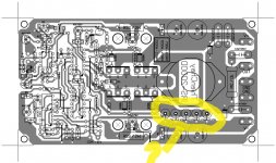
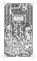
Can Somebody post real pcb layout of IRS3000D I was looking layout of irs2000 and I am confused with some resistors I dont see on the original IRS3000d design but see on this Layout?
Regards
Regards
Attachments
Last edited:
my amp have 900W at 4 Ohm RMS
if output filter goes hot, what can do to solve problem ?
1. Change switching frequency from 200 to 350 khz
2. or change mosfets
If output filter gets hot, you need a better core for the inductor. Or you can try to lower, not increase the switching frequency.
hy
can u please send me the pcb and schematic.thank you
Hi Dzony988,
yes I'm using LM311 and its a carrier based class d amp not UCD(self osc).fsw=250KHz or you can change fsw and no noise issues. if you want it PM me
Regards
MANOJ
can u please send me the pcb and schematic.thank you
my amp have 900W at 4 Ohm RMS
if output filter goes hot, what can do to solve problem ?
1. Change switching frequency from 200 to 350 khz
2. or change mosfets
It heats at idle or at good power ? What heats more - the core or the winding?
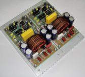
my current project i decided to go non ucd way 
Attachments
-
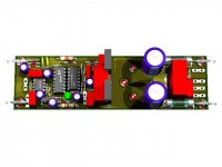 gtG 800.jpg62.3 KB · Views: 883
 -
gtG 800 schematic.pdf28.4 KB · Views: 955
-
gtG 800 components clear.pdf24.4 KB · Views: 559
-
gtG 800 components full.pdf26.3 KB · Views: 649
-
gtG 800 pcb artwork 2 smll.pdf388.8 KB · Views: 911
-
gtG 800 pcb artwork smll.pdf308.3 KB · Views: 1,043
-
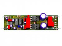 gtG 800 2.jpg63.6 KB · Views: 1,798
i decided to go non ucd way
Hi Stewin,
Sigma Delta design is good for all
NB: using BIAS +15V you should reduce the value R13 to @250KHz FSW range
Regards
MANOJ
Hi Stewin,
Sigma Delta design is good for all
NB: using BIAS +15V you should reduce the value R13 to @250KHz FSW range
Regards
MANOJ
thanks sir manoj originally i had planned to use irfb4227 or irfp4668 .but since i am using irfp250n i will change the swithching frequency.
also i wanted to reduce fsw by using 820ohms to about 200 khz so as to drive the amp harder
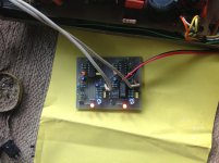
.. thanks again for the correction. i will post the smps i am developing
.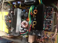
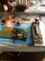
Hi Steven
detex smps is now working today i do some load tests
warm regards
andrew
Hello adrew can You please post detex smps 3kw with TL494 layout pcb
thanks
yes, i like this smpsHello adrew can You please post detex smps 3kw with TL494 layout pcb
thanks
- Home
- Amplifiers
- Class D
- UCD 25 watts to 1200 watts using 2 mosfets