just wondering are the below layouts up to the standard

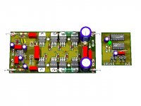
Just this one is little bit ok from others in the pics.
But missing bulk capacitance for rails.
Last edited:
Just this one is little bit ok from others in the pics.
But missing bulk capacitance for rails.
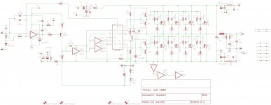
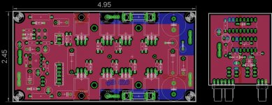
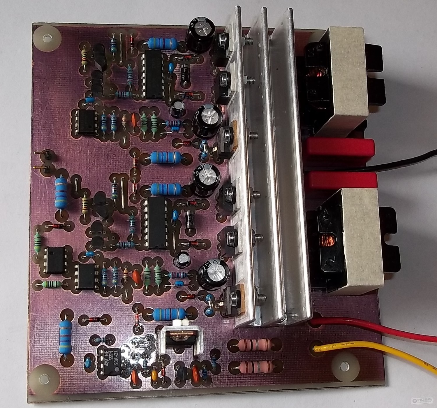
This is from the Hungarian forum. It is made by a member called Ge Lee there. As stewin and others can see: minimal tracks, good placing, and proper ground plane.
As Workhorse noted, there ar no bulk capacitors, and Ge lee realized it. At high loads, distortion increases, partly because of suppply drop and spikes due to long paths.
He soldered MKP capacitors on the bottom of the PCB, just to MOSFET legs, which helped this. He experimented with more X7R caps at 1812 size, according to him, this did not improve much. MKP has much lower ESR and dissipative factor than X7R.
But X7R is very dependent on manufacturer. This code is not exactly the material, but the temperature and tolerance classes.
I also experimented with MKP caps, but my 1812 sized 330nF 100V X7R caps were good for coupling, right next to MOSFET legs. I also used multiple 220uF 100V LOW-ESR elcos near (distance<1cm).


-+90vnice work vonghai.
is it working ? what voltage and output mos-fets have you used also what is your speaker impedance?
2ohm
mình viết tiếng anh không được
kéo full speaker với tải 2ohm mos-fets không nóng
that is not right... that voltage, 4R load is about 1kw, and into 2R is double that, so 2kwWow, isn't +/-90 volts into 2 ohms the same as (180 volts)^2/2ohm = 16.2kW!!!
Isn't power equal to V^2/R (Ohm's law)
If driven at full rail-to-rail of +/- 90 volts is same as 180 volts
180^2/2=16200. Even at 4 ohms it is 8100.
What am I missing here?
Theoretical max amp power = V peak peak ^2/8*R = 180^2/16 = 2025 W
Cheers ,
Rens
Isn't power equal to V^2/R (Ohm's law)
If driven at full rail-to-rail of +/- 90 volts is same as 180 volts
180^2/2=16200. Even at 4 ohms it is 8100.
What am I missing here?
RMS power is = (180/sqrt2)^2/2 = 8100 (BTL) , (90/sqrt2)^2/2 = 2025 W ( halfbridge)

You guys are throwing formulas around - show me where they come from please. As far as I know rms of power is simply sqrt(2)/2 or 0.707 times the peak power. Let's assume 1 kHz sine wave which is how power is specified as usually. Half bridge full bridge - why is that even a consideration for an amp that is making a sine wave audio signal. We are not talking about AC line power and power factors are we?
Here is the reference for RMS Power from TI for class D amps.
Using their equation on page 4 I get 8kW still.
http://www.ti.com/lit/an/slea047a/slea047a.pdf
Peak current is 180 volts /2 ohms = 90 amps. 90 amps x 0.707 = 63.6 amps. 63.6 amps ^2 x 2 ohms = 8kW.
Here is the reference for RMS Power from TI for class D amps.
Using their equation on page 4 I get 8kW still.
http://www.ti.com/lit/an/slea047a/slea047a.pdf
Peak current is 180 volts /2 ohms = 90 amps. 90 amps x 0.707 = 63.6 amps. 63.6 amps ^2 x 2 ohms = 8kW.
Last edited:
- Home
- Amplifiers
- Class D
- UCD 25 watts to 1200 watts using 2 mosfets