Thanks! That's why I've been working with decent ordinary parts for repeatable results fairly easily.You Sir are awesome! Many higher-level DIYers forget that this hobby is confusing and complex for the newbie. Your work provides a perfect entry point.
It's also great for those who are pressed for time, wish to start from a known-good platform and do some experimenting ...")
Storm? Have you cranked one of these up yet? The parallel TDA7294S/TDA7293 board is ready to go for hi-fi.Throw in: cheap, widely available PCB; interesting chip that provides for some learning, expansion and testing; and the Energizer Bunny of hands-on testing ... a perfect storm of DIY!
I'm still tuning on the solo model, but there's good progress and cool temps. Just checked it at full blast. I'm not done yet. Next step, moving the gain divider resistors underneath for an effective sound quality upgrade that doesn't cost anything.
P.S.
TDA729X has a baby brother: http://www.diyaudio.com/forums/class-d/231988-what-heck-its-less-than-lunch.html#post3409339 <--link. The little $8 Class AB is posted in the Class D forum, as a competitor/comparison on audio quality and the results are super funny!
Ah, don't forget the Nichicon ES (little green bipolar Muse electrolytic) in 1uF and 0.47uF sizes. They work normally, fit easily and have clean high resolution. Just the thing for prototyping stuff and not have to wonder about your input cap quality. At Mouser they are 26 cents (the 10 spot price is 17 cents per cap), and the canister width is just 5mm. They can also be used to bypass larger electrolytic caps and work easily for that.
Thank you Daniel. I will look at the capacitors you mentioned. I will need a small quantity of 0.47 and 1 uF coupling caps for my build, and the smaller the better. I am struggling right now figuring out how to fit all the parts. The local electrolytic voicing caps I'm considering (between 220 and 470 uF, probably closer to 220 uF) are 10 cm diameter and with six of them per board that's 25% of the space right there.
I am still curious about exactly what resistor you used in the feedback loop that was so bad. Metal film resistors are de rigueur in audio circuits today and they are not all created equal. I agree that linearity in the audio band (actually up to 100 kHz or even higher depending on the Bode plot) is a paramount consideration. But if you look at the data sheets you will see that some are not manufactured as non-inductive. These resistors obviously do not belong in an audio feedback circuit.
Metal film resistors are manufactured by depositing a film of specified thickness and then that film is precision etched in a spiral pattern. So it should be apparent why there could be some issues with metal film resistors (even those that are advertised as "non-inductive") similar to wirewound resistors. Of course the small scale of metal film vs wirewound will allow much higher resistances with less inductive effect, but a good rule of thumb is to keep values as low as practical, which will mitigate the effect of any inductive (or capacitive) effects.
Hi Eddie,
I've got a question about shelving the gain. For example, I'm having trouble with the TDA7294 solo, trimming it to get both good bass and good treble. If I use, for example, 27k vs 820R, 34X, good bass and no sparkle, then approximately what values for supplementary RC to shelve slightly above the audio band, back up to 42X? I'd sure like some ballpark values for a place to start.
I've got a question about shelving the gain. For example, I'm having trouble with the TDA7294 solo, trimming it to get both good bass and good treble. If I use, for example, 27k vs 820R, 34X, good bass and no sparkle, then approximately what values for supplementary RC to shelve slightly above the audio band, back up to 42X? I'd sure like some ballpark values for a place to start.
Well Daniel, it seems that they have not provided a Bode plot with the datasheet. While this chip certainly looks promising, it is difficult to devise such schemes "on paper" without pertinent information. From what I can glean from the data sheets, this device is highly optimised for audio use and is very slow. It is difficult to apply such techniques to slow devices, for reasons we have already discussed; they were originally used on fast but cranky op amps for low gain or buffer applications. You need a lot of bandwidth to implement it without comprimising stability.
I hope you are breadboarding, because you might be able to balance the sound of your amplifier with a modest application of this technique. Try a 3 dB shelf with a lower turnover frequency of maybe 70 kHz or so. This will intrude on the audio band, but the tradeoff might be worth it. From the looks of the available data it appears that the bandwidth drops off after 100 kHz, which suggests a slope of 6 dB/ octave starting there. You don't have a lot of bandwidth to work with, so think small shelf and low turnover frequency.
I hope you have a scope but if you don't, you can tell if it's oscillating by the snubber resistor. It should never get hot, even if it's just an ordinary half watt resistor. But if it gets warm or hot, it;'s oscillating.
We are flying blind without proper data, so you will have to determine the virtue of this application empirically. It may make it worse, it may make it better; it may have no subjective effect, or it may oscillate. It is your risk and your responsibility to determine the virtue of this technique.
I am definately going to explore this myself with the LM1875, but I have to order a lot of parts first. Plus my shop space is dedicated to chassis fabrication and layout planning right now. But it's on my short list.
Personally I do not think that this technique has much promise for these various power amp chips. They are highly optimised for their intended application and are slow and limited in bandwith for predictable performance with this technique. Still, it might offer some small benefit and since parts are cheap and I dig the research I am going to do some informal exploration.
Last edited:
Hi Eddie,
Like Kean mentioned earlier, I suppose we'd need an input RF filter in order to avoid phase related errata (aka tilt-a-whirl imaging)?
When I try to calc gain comp assisted by shelving the gain. . .
Run the amp to "max but not more" by 70khz
Result:
47k vs (6.8k+330p)//(1.36k+681u)
or
39k vs (6.8k+330p)//(1.10k+681u)
By any chance, did I calc this right?
What a weird concept--actually trying to calculate an audio amplifier to Sound pretty.
Now to the soldering iron to find out what happens. . .
Last edited:
That's a lot too strong. And like every good compensation, needs more compensation added. Howabout an alternative?
pin2 to feedback-shunt resistor to resistor paralleled with tiny cap, to nfb-shunt cap
Is that a bit more tame?
Edit: Meanwhile. . . it is possible to do gain 38x with a much simpler comp or none.
47k vs 1.27k
1.27k is 1k series to 270R
Gain 38x.
A little bit of input RF filter and an extremely tiny dose of lead lag like with 2k7+220p, may get the job done.
I'm checking. . .
Edit2: Yep.
Last edited:
Progress Report, 1-chip TDA7294V board
Still having a fight with the solo board.
Current difference:
With the settings that worked for the Parallel board (27k vs 730R) the Solo board exhibited front end overcurrent symptoms, treble droop and a midbass blur. Of course, the front end or predrive section of the Solo chip is working harder because of much less output current buffer.
Current compensation:
So I tried 47k vs 1.270k for the solo board, in an attempt to resolve the current discrepancy. This is meritorious for tone and sounds similar to the parallel board for mids and treble. However, the solo board plays with the same good bass. . . until you turn it up and the bass goes missing. Is it the on-chip limiter or is it undercurrent from somewhere else?
Still working on the solo:
I need to find the bass. Possibilities include, average of the above two settings, array at the power circuit, bootstrap cap, shield section piece added to the power circuit, separate the front end power, or my chip might be a re-mark, or perhaps it is working normally. I do not know yet. Still exploring.
Eddie's approach really did resolve the bass and tone issues and it provided interesting imaging; however, it also requires additional compensation for which I don't have the skills or tools.
Schematic, and some options.
I'm probably about to "go on break" for a short time (test stuff not at same local as enough parts), so here is the TDA7294 at an even balance setting.
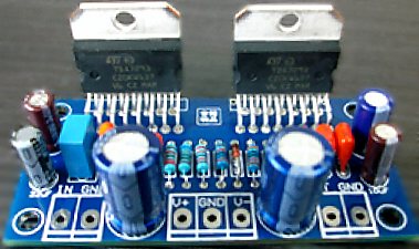
And here's what the board looks like with the components on it.
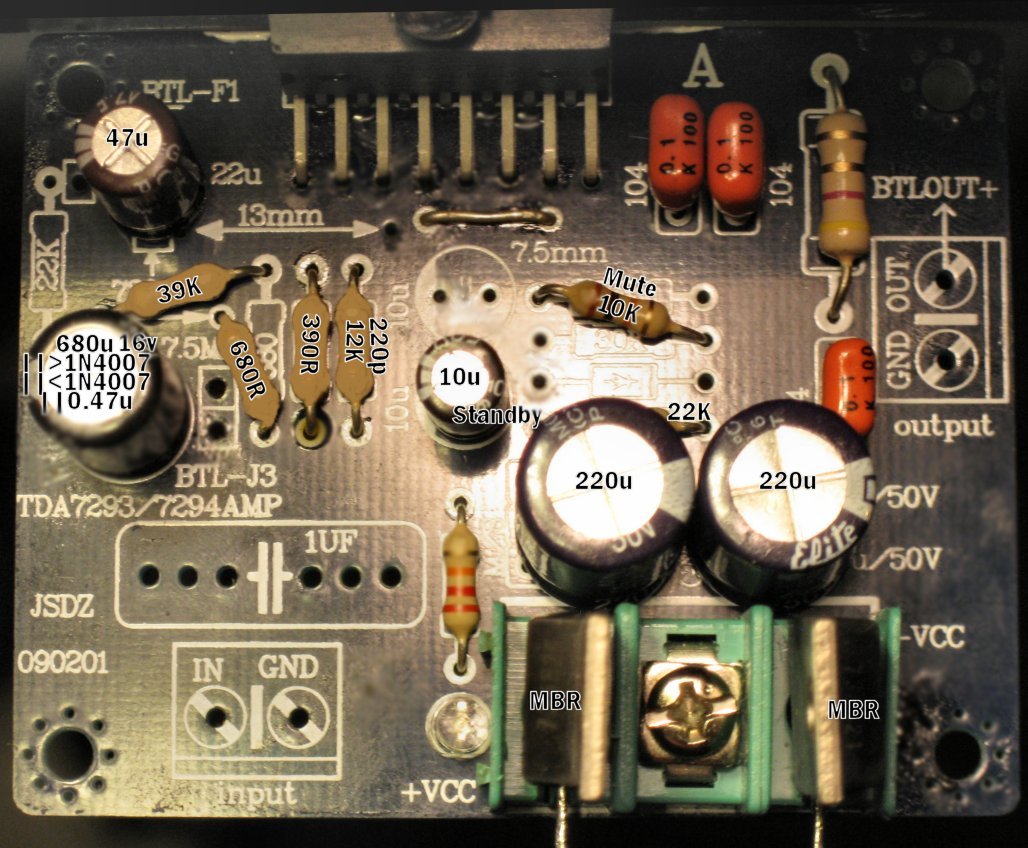
Of course, you could get better results by subtracting the sound of the board like this: Relocate the 39K feedback resistor directly onto the chip, pin14, pin2, and then also relocate feedback-shunt resistor(s), bottom side of the board, in a direct line from pin2 to NFB-Shunt Cap. It fits easily.
The input load of 12k shown is for direct drive from computer, but you can change it anywhere in the range of 10k to 33k, and the factory equipped 22k is the average anyway.
At 35+35vdc rails, the amplifier has a gain range of 37.5X to 42X. However, if using lower voltage, you may be able to set it for lower gain--do set it low enough for good bass but don't set it low enough for treble droop. That's easier at lower voltage which makes available a greater variety of settings that work.
At feedback-Shunt, Instead of 680R resistor series to 390R resistor for trim, you might really like to replace that with resistor series to trimmer for adjustable gain fine tuning, like this: 1k resistor series to 200 ohm multi-turn trimmer/potentiometer (center pin of trimmer soldered to one of the outboard pins of the trimmer creates a variable resistor).
That will let you dial the gain from 33.5x to 40x, so just dial the gain as low as you can without causing treble droop and you've got it. Just glue the 200 ohm trimmer, under board, right next to the NFB-Shunt cap (and connect to cap+), and then reach the 1k resistor from trimmer to pin2.
Don't worry about the multi-turn trimmer's affect on quality; those are composite material. Now, your FB-Shunt resistor is variable; and, I highly recommend an adjustable gain upgrade because your operating voltage, personal preferences and speaker load might be different from mine.
P.S.
I'm not yet ready to declare that this is penultimate, so while "on break," I'm fetching more parts to try more stuff later. I need to complete two additional explorations, small signal on array power and also bootstrap cap value versus all of the other parameters; because the bootstrap value will change the tone--Likewise so does the operating voltage. However, the above very simple schematic really does show off a bit. Let's call it a "sneak preview."
I'm probably about to "go on break" for a short time (test stuff not at same local as enough parts), so here is the TDA7294 at an even balance setting.
And here's what the board looks like with the components on it.
Of course, you could get better results by subtracting the sound of the board like this: Relocate the 39K feedback resistor directly onto the chip, pin14, pin2, and then also relocate feedback-shunt resistor(s), bottom side of the board, in a direct line from pin2 to NFB-Shunt Cap. It fits easily.
The input load of 12k shown is for direct drive from computer, but you can change it anywhere in the range of 10k to 33k, and the factory equipped 22k is the average anyway.
At 35+35vdc rails, the amplifier has a gain range of 37.5X to 42X. However, if using lower voltage, you may be able to set it for lower gain--do set it low enough for good bass but don't set it low enough for treble droop. That's easier at lower voltage which makes available a greater variety of settings that work.
At feedback-Shunt, Instead of 680R resistor series to 390R resistor for trim, you might really like to replace that with resistor series to trimmer for adjustable gain fine tuning, like this: 1k resistor series to 200 ohm multi-turn trimmer/potentiometer (center pin of trimmer soldered to one of the outboard pins of the trimmer creates a variable resistor).
That will let you dial the gain from 33.5x to 40x, so just dial the gain as low as you can without causing treble droop and you've got it. Just glue the 200 ohm trimmer, under board, right next to the NFB-Shunt cap (and connect to cap+), and then reach the 1k resistor from trimmer to pin2.
Don't worry about the multi-turn trimmer's affect on quality; those are composite material. Now, your FB-Shunt resistor is variable; and, I highly recommend an adjustable gain upgrade because your operating voltage, personal preferences and speaker load might be different from mine.
P.S.
I'm not yet ready to declare that this is penultimate, so while "on break," I'm fetching more parts to try more stuff later. I need to complete two additional explorations, small signal on array power and also bootstrap cap value versus all of the other parameters; because the bootstrap value will change the tone--Likewise so does the operating voltage. However, the above very simple schematic really does show off a bit. Let's call it a "sneak preview."
Attachments

Or would you rather have a stable amplifier? Stable sounds better to me.
Thanks to Kean who spent a long time teaching me about compensations. I've been working on this all day long, and now you have much better sounding and much more powerful amplifier. They run better when stable.
That little RC (15R+82n shown from pin2 to pin3) will do more for your sound quality than any amount of audiophile caps. It takes a bit of precision to do lead lag comp with a chip amp, so if you change anything, you may also have to change the 82n to a value slightly lower or higher. When you purchase this cap, I suggest to also purchase options of a 100n in case you set the gain slightly lower and a 68n in case you set the gain slightly higher. For reference, I used 25+25vac 8 ampere transformer and an 8 ohm speaker, and this amp has been synchronized for high dynamic power. Input load does make a small tonal difference; so, depending on your source, you might rather have a 12k or 22k or 27k input load resistor for the amp.
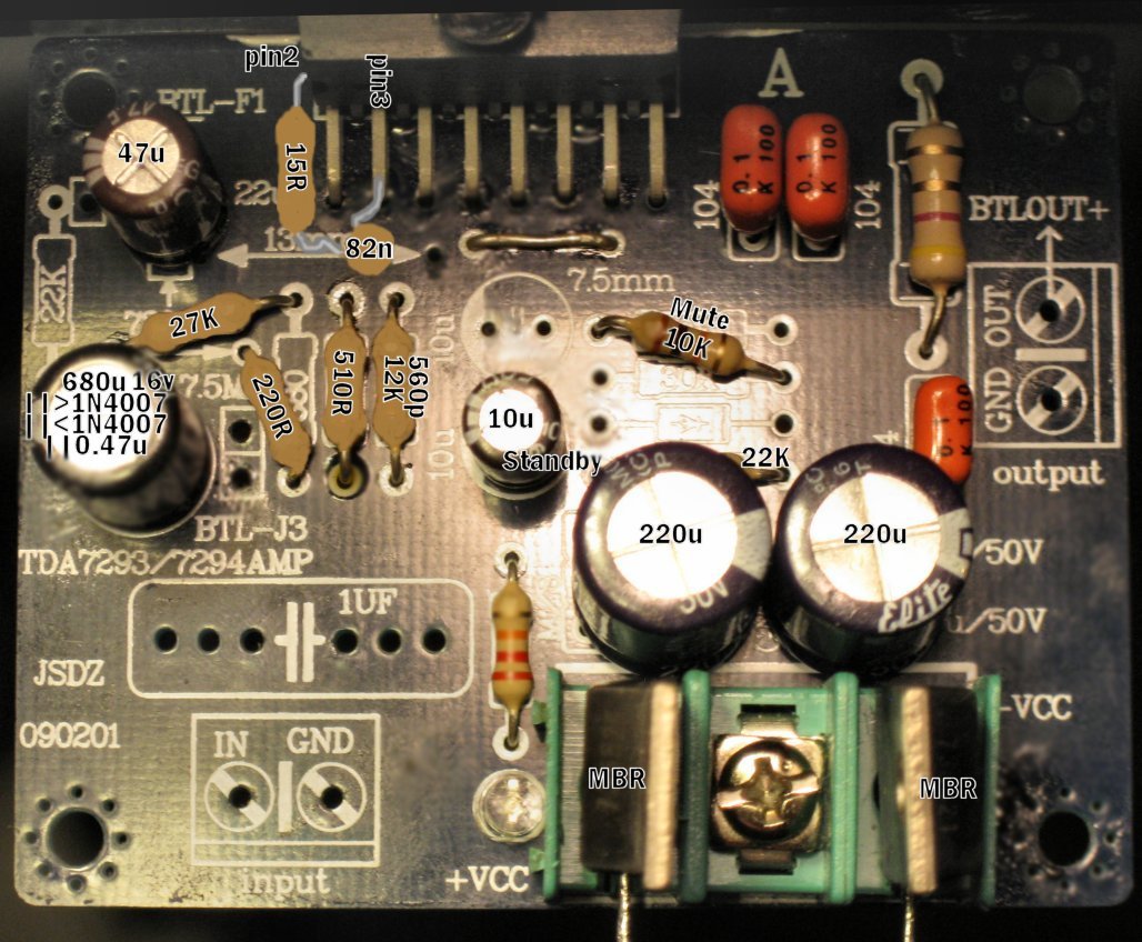
The actual test sample has the feedback shunt resistors underneath the board from pin2 to NFB-shunt cap, and the feedback resistor is directly on the chip from pin2 to pin14, and thus no "board sound" at all. However, now that the amp is stable it is also less sensitive to layout differences.
Bob,
This one is ready for your review.
See how it competes against the MyRef?
Thanks to Kean who spent a long time teaching me about compensations. I've been working on this all day long, and now you have much better sounding and much more powerful amplifier. They run better when stable.
That little RC (15R+82n shown from pin2 to pin3) will do more for your sound quality than any amount of audiophile caps. It takes a bit of precision to do lead lag comp with a chip amp, so if you change anything, you may also have to change the 82n to a value slightly lower or higher. When you purchase this cap, I suggest to also purchase options of a 100n in case you set the gain slightly lower and a 68n in case you set the gain slightly higher. For reference, I used 25+25vac 8 ampere transformer and an 8 ohm speaker, and this amp has been synchronized for high dynamic power. Input load does make a small tonal difference; so, depending on your source, you might rather have a 12k or 22k or 27k input load resistor for the amp.
The actual test sample has the feedback shunt resistors underneath the board from pin2 to NFB-shunt cap, and the feedback resistor is directly on the chip from pin2 to pin14, and thus no "board sound" at all. However, now that the amp is stable it is also less sensitive to layout differences.
Bob,
This one is ready for your review.
See how it competes against the MyRef?
Attachments

Last edited:
Array power and prettier sound.
Packing my suitcase, rounding up the critters and heading to the farm today, Before I go, I thought I'd try bracing up the front end shield with a simplified array in order to dial back the compensation for a faster speed. Arrays are good in theory, but making them work usually involves active devices for series elements. This was astonishingly easy. . .
Cleaner
I changed the MBR schottky to ordinary old 6A05's from the radio shack. No need for the terminal block. These diodes plug right in to the V+ and V- pads of the amplifier board. V+ diode's stripe touches the board. V- diode points away from the board. DC cable connects to these. 0v is connected direct to the board's 0v pad normally. Now we can add more reservoir aboard for more clean power like this:
Stronger
Under the board, I soldered an additional set of 220uF capacitors. Now the power circuit has 220u||220u (low loss quick 440u) per each rail. That's your array power and it looks like: A set of 220u capacitors on top of the board AND again on the bottom of the board (high quality 440u per each rail). The diodes have allowed array power to work quickly, and likewise, regulators (optional) should work as well.
Faster
With the stronger shield providing better dampening (darn that single layer board!!), enough ringing has been removed, that now we can set the cruise control to higher speed--change the 82n lead lag cap to 47n (you can test drive 39n for treble difference). Wow, much less compensation needed.
Board issues
I cannot do more for the Jim's Audio TDA7294 single layer + mad pinout = disaster layout board, because the need of added compensation is board layout related. Please, please on new builds, choose the TDA7293 Parallel which has a better performing layout, greater linearity, twice the power and half the price. No wonder Klaus and Tom went all enthusiastic over power and layout. Yes, if you want a better amp, get a better board.
Okay. I'm off to the farm now.
Here's the corrected and stabilized schematic for the single layer Jim's Audio TDA7294 kit.
Attachments
Last edited:
Geeze, are you sure you don't want to try different types of power supply caps while you're waiting for the car to warm-up?
... just go already!!!
Thanks for hammering it out before you left, I've ordered a pair of the parallels and I'll chime in after a few weeks.
Thanks Kean!
Any chance we could try for a lower gain version x20 or x10?
Enjoy your trip!
Thanks,
Jeff
... just go already!!!
Thanks for hammering it out before you left, I've ordered a pair of the parallels and I'll chime in after a few weeks.
Thanks Kean!
Any chance we could try for a lower gain version x20 or x10?
Enjoy your trip!
Thanks,
Jeff
Jeff - What particular parallel did you order. I'm about to pull the trigger on one too, but want to get the best one.Geeze, are you sure you don't want to try different types of power supply caps while you're waiting for the car to warm-up?
... just go already!!!
Thanks for hammering it out before you left, I've ordered a pair of the parallels and I'll chime in after a few weeks.
Thanks Kean!
Any chance we could try for a lower gain version x20 or x10?
Enjoy your trip!
Thanks,
Jeff
But, then I expect Daniel to make it better. Wow! I have to publicly thank Daniel not only for all the effort and time he has applied to this thread, but also my appreciation for keeping the thread itself alive and moving forward.
The parts I don't have will be in my next order and I'm anxious to hear the improvements.
You guys are great!
(I'll PM Klaus for info. He did say it was more of a long time project. I'm sure the interest is still there)
The parts I don't have will be in my next order and I'm anxious to hear the improvements.
You guys are great!
(I'll PM Klaus for info. He did say it was more of a long time project. I'm sure the interest is still there)
I hope that is this board. The behavior is really nice. And a link: TDA7293 170W | eBayJeff - What particular parallel did you order. I'm about to pull the trigger on one too, but want to get the best one.
That's the board that I'm fine tuning with intention to use it for refitting my Technics receiver.
For the lead lag comp used to tame that single layer TDA7294v board, you might want a selection of 47n, 39n, 33n, 25n, 22n caps so you can fine tune the compensation. Different operating voltage, and different cap efficiencies affect the board differently, and so that would change the need of compensation as well. Smaller cap value = less compensation. Basically choose the cap value in that range for neither too little nor too much treble. Insufficient treble or uncomfortable weird ear pressure is unstable or ringing--cap is too small, but too much treble is cap too large.bcmbob said:The parts I don't have will be in my next order and I'm anxious to hear the improvements.
Adjustable gain, is really helpful when trying to sync compensation. It replaces the 510R+220R Feedback-Shunt resistor seen on the schematic. Instead of the fixed value, we make the Feedback-Shunt resistor adjustable (within a practical range). To install that, you just put 1 outboard pin of a 100R multi-turn trimmer right on the NFB-shunt cap "+", and then glue the trimmer down to the board, and then the other two pins (center pin plus opposite outboard pin of the trimmer) connect to a 680R, which then goes in a straight line, right over to pin2 of the chip. This is really easy. It is the same for both boards. A 200R trimmer can be used, if your amp is under-volted.
Last edited:
I just searched ebay for "TDA7293 Parallel" ($20) but I did find a slightly cheaper one ($15):
TDA7293 x2pcs 170W Mono amplifier board Kit -29
TDA7293 x2pcs 170W Mono Amplifier Board Kit 29 | eBay
If you really wanna commit, here's a super-cheap 5 pack (home theatre!)
5 PCx Assembled Finished 170w TDA7293*2 Dual Parallel Mono power amplifier board
5 PCX Assembled Finished 170W TDA7293 2 Dual Parallel Mono Power Amplifier Board | eBay
TDA7294
[SIZE="<font><font>4</font></font>"]PCB 240W Stereo Amplifier TDA7294 Yiroshi. Design and Redesign YIROSHI mnicolau[/SIZE]
TDA 7294 STEREO AMPLIFIER 240W
regards.
I hope that is this board. The behavior is really nice. And a link: TDA7293 170W | eBay
That's the board that I'm fine tuning with intention to use it for refitting my Technics receiver.
For the lead lag comp used to tame that single layer TDA7294v board, you might want a selection of 47n, 39n, 33n, 25n, 22n caps so you can fine tune the compensation. Different operating voltage, and different cap efficiencies affect the board differently, and so that would change the need of compensation as well. Smaller cap value = less compensation. Basically choose the cap value in that range for neither too little nor too much treble. Insufficient treble or uncomfortable weird ear pressure is unstable or ringing--cap is too small, but too much treble is cap too large.
Adjustable gain, is really helpful when trying to sync compensation. It replaces the 510R+220R Feedback-Shunt resistor seen on the schematic. Instead of the fixed value, we make the Feedback-Shunt resistor adjustable (within a practical range). To install that, you just put 1 outboard pin of a 100R multi-turn trimmer right on the NFB-shunt cap "+", and then glue the trimmer down to the board, and then the other two pins (center pin plus opposite outboard pin of the trimmer) connect to a 680R, which then goes in a straight line, right over to pin2 of the chip. This is really easy. It is the same for both boards. A 200R trimmer can be used, if your amp is under-volted.
[SIZE="<font><font>4</font></font>"]PCB 240W Stereo Amplifier TDA7294 Yiroshi. Design and Redesign YIROSHI mnicolau[/SIZE]
TDA 7294 STEREO AMPLIFIER 240W
regards.
Good!This is the one I ended up ordering.
Kean and I have that board too. I guess Zoe re-stocked pretty fast.
Yes! This well illustrates the need of installing adjustable gain. Of course, low gain will sound as dreadful as the datasheet sample design. However, the trimmer dial would let you install the desire for low gain and still be able to dial in appropriate quality anyway (at higher gain, of course). In addition to so easily resolving that conflict, you can use the dial to precisely synchronize compensations. And, ideal gain varies by both rail voltage and load too. So, I think that adjustable gain should be mandatory.AudioLapDance said:Any chance we could try for a lower gain version x20 or x10?
TDA7294 can use a gain range of 38X~40X in non-inverting mode, or it can use somewhat lower gain in inverting mode, which also needs a transistor buffer added. TDA7294S/TDA7293 has an optional 1X gain mode, which is where the onboard front end is disabled and you add a replacement front end externally, from tubes or transistors or op-amp.
Except for the 1X option, low gain means first ruin the quality and then apply greater negative feedback to recoup some but not all of the quality. Basically, it is a voltage amp, and asking it not to amplify voltage is asking it not to work. That has a few caveats. Low gain can also be done by severely under-volting the amp, but that has the caveat of a lot less output power, which is yet another way to do a lot less amplifier.
Once again, the Honey Badger discrete amplifier has a gain of 41X, and so our gain of 38X is three times less voltage amplification. Given a 1v source, such as a computer, and not running the source all the way to faltering/clipping then means that we need gain in the upper 30's for the power amp to reach the rails. In the most common applications, our 38X is only slightly too much. Even so, I think that adjustable gain is quite important so that you can determine these factors for yourself.
Adding the trimmer is a lot more powerful for audio quality than any amount of audiophile parts. A multi-turn trimmer at feedback-shunt for adjustable gain can let you dial in appropriate standard gain comp to support your specific operating voltage and speaker load. Adjustable gain used for system symmetry will get optimal performance from the TDA729X family. Conversely, arbitrary fixed settings will not result in optimal performance. SO, it seems that we shall need that dial.
Last edited:
- Status
- This old topic is closed. If you want to reopen this topic, contact a moderator using the "Report Post" button.
- Home
- Amplifiers
- Chip Amps
- Optimizing TDA7294 Output