......I found snubbing the 14KHz resonance made the biggest impact on sonics. .......
Is it possible for you to put up a pic of the normal / snubbed resonance ? Where are you measuring ? Directly at trafo output ?
Great idea for using a 'sniffer type' coil to 'hear' the difference !
Thanks.
Let me describe my test setup. My signal generator is a Tektronix FG504. My scope is a Tektronix 465B. Neither are in great condition but they work. I blew the internal fuse on my FG504, which I cannot find a replacement for, so I replaced it with a carbon comp 3.3R resistor. Coax termination and attenuator calibration may be slightly off, but it's still flat within the audio band.
Rail resonances and trafo resonance since they are typically parallel impedances, are damped by low resistances and should be measured with a high impedance signal source. So I use a 1k carbon comp resistor in series with the SG output. I use carbon comp because I'm distrustful of film resistors with a coil-shaped track. This still doesn't matter at 14KHz, but I have also measured resonances in the 1MHz-40MHz range where it does. Rail resonances typically have impedance below 2R so a standard 50R SG impedance will do fine for identifying resonances.
When I do the test I leave everything about the supply as is, and the ground on the secondary side is floating. The decoupling and everything on the secondary side of the rectifier affects the secondary resonance. I connect the SG and scope ground together at one side of the seconary and SG output and scope input at the other side of the secondary. Then I sweep the frequency, looking for peaking.
The voltage at this point can't get too large or the rectifiers will switch on. It is resonance in the off-state that we are measuring.
Daniel, the PS in post #220 looks straight forward and easy to construct. What is the expected nominal DC output of that configuration?
I too am finishing a discrete project that requires ~ 35 -50 VDC, and it would be great to be able to use the "old gal" as a bench PS for both the TDA and the discrete. Is that a possibility with this design?
I too am finishing a discrete project that requires ~ 35 -50 VDC, and it would be great to be able to use the "old gal" as a bench PS for both the TDA and the discrete. Is that a possibility with this design?
For dual secondaries transformer, it would have been a lot easier with a pair of KBPC1004 bridge rectifiers instead of the discrete mess of 8 diodes.Daniel, the PS in post #220 looks straight forward and easy to construct.
Yes, I'm doing the same thing.What is the expected nominal DC output of that configuration? I too am finishing a discrete project that requires ~ 35 -50 VDC, and it would be great to be able to use the "old gal" as a bench PS for both the TDA and the discrete. Is that a possibility with this design?
This is derated for voltage so that caps last longer:
With 50v caps, about 9vdc~35vdc per rail.
With 63v caps, about 9vdc~48vdc per rail.
Or you could use 80v rated capacitors or 100v rated capacitors if you want to.
See capacitor datasheet for more information on the amount of hours it may last at a given voltage.
Meanwhile, back to the topic of an RC (or RCR) from "~" to "~" at the KBPC1004 bridge rectifier, and I haven't given up on the prospect of "muffle the AC, not the audio."
Best explanation of a snubber, ever. And, quite doable!Again, capacitance does not snub. . .
NOTE: The resistor, alone, is all that is needed to prevent or damp-out the ringing (or reflections, as the case may be). But if power dissipation in the R would then be too high, a C is added in series with the R, so that only the unwanted frequencies cause currents in the resistor. (And that is the only reason there's a capacitor in a snubber.)
If I understand correctly, the parameters are to do something beneficial, without getting the resistor too hot. Well, that's not complicated at all. Thanks!!
P.S.
I think we should notice some sort of benefit, such as less heat output at the amplifier heatsink or clearer audio; and with a typical TDA7294, cleaner power will probably do both benefits.
Last edited:
The resistors weren't defective.
Measuring for hours to find non-defective resistors, but the problem was layout. Apparently any amount of excess resistor pin length changes the crc resistor value. Need to bring the copper rods Up through the board and against the sides of the big resistors to minimize pin length. Conveniently, the resistors stack up vertically. I'll probably mount the bypass diode trackside (underneath) so that I can adjust either voltage (diode) or current (resistor) without having to disassemble both.
P.S.
Digital multimeter was helplessly measuring its own test leads; however, ESR meter can be zeroed to negate the test leads and it resolved that the resistor values were reliant on practically zilch for pin length. So, the big search for resistors was over. All of the resistors were fine. But, I need to go to the garage for some nice thick romex solid copper.
Anyway, without some attention to detail, the prospect of using multiple resistors in parallel for lower inductance can be self-defeating if there is excess resistor pin length involved.
I have failed many amplifier builds this last few weeks. For my own discrete designs I can accept it. But for chip amps!? I couldn't even solve the problem!!!? Or may be because I didn't expect failure, I didn't have the motivation to fix it.
SK3875 (Sony Gainclone) - Failed on both channels, no troubleshooting, thrown away after failure to produce sound.
LA4450 - Failed one channel. From quick troubleshooting I thought it was chip issue. Not too good anyway.
SK18752 (Sony Gainclone) - High voltage on output, both on single supply and dual supply application. I'm pissed.
TDA2030A - No sound on both channels. Geez.
TDA2009 - Using IBM laptop power supply and local bypassing (A-la Amp Camp Amp#1), powerboating, kewwl %$#%@
LM4766 - Half way to finish. Too tired of the previous failures
TDA7294 - Originally it was working just fine for about 2 days. Then I built another amp. Then I wanted to compare the new amp with the TDA7294, but no sound!! As if the amp is muted. But if power supply is disconnected, after a few minutes, there is a burst of signal flowing through the speaker. I replaced the caps one by one but same symptoms happened. Arggh... please help... what could be the problem with the capacitor symptom...?
Perhaps an adjustable voltage power supply of some sort used for test but glitches every so often releasing the maximum voltage? Or, perhaps music source has strong offset or high power HF output? Or perhaps some randomly occurring short at the speaker?
Need to try that TDA7294 with big caps series to the speaker (if there was previously dc offset or dc offset surge and you block that, it may play). Definitely need to try a different speaker. Need to check out the power supply or try a different power supply. And need to try a different music source. Light bulb test might also be informative. Got led's on both power supply rails?--those can also be somewhat informative.
Need to try that TDA7294 with big caps series to the speaker (if there was previously dc offset or dc offset surge and you block that, it may play). Definitely need to try a different speaker. Need to check out the power supply or try a different power supply. And need to try a different music source. Light bulb test might also be informative. Got led's on both power supply rails?--those can also be somewhat informative.
Daniel, on post #220 you are showing cement resistors. Was there a reason for that other than that's what you had on hand? The Mouser links you sent me are not.
Ceramic/Cemented resistors in values Larger than 0.25R are unfortunately inductive. But, the item in that link is 0.24R, and can work fine. By the time the pins go down through the perfboard to reach the rail, it may be 0.27R and probably still just fine. It can't handle the power up surges all by itself, but the diode takes the brunt of the surge.Daniel, on post #220 you are showing cement resistors. Was there a reason for that other than that's what you had on hand? The Mouser links you sent me are not.
I'm planning to upgrade mine to 4 or 5 of "metal oxide 3w" per rail: MOS3CT631R132J KOA Speer | Mouser as specified by the schematic in post 218, and installed as specified at post 225.
4 paralleled 1.3 ohm 3W metal oxide resistor makes: 0.33 ohms 12 W
5 paralleled 1.3 ohm 3W metal oxide resistor makes: 0.26 ohms 15 W
SO, you see that the schematic at post 218 has a high power, low cost, non-inductive resistor that can be value tweaked without disassembly.
The metal oxide resistors don't have a big surge tolerance; however, again the diode takes the brunt of the surge.
----------------------------------------------
The above resistors measure current, but resistors don't really measure voltage, and music signal is highly dynamic, so that any resistor setting is always simultaneously too much and not enough. CRC Resistors react to dynamics, especially bass dynamics, by dumping them like throwing the baby out with the bath water. Fortunately, the bypass diode limits the voltage losses.
This limits the crc resistor's rail sag to a voltage setting of your choice.
Fast silicon diode is about 0.45v (use with small amplifier)
6a and 10a standard diodes are about 0.6v (use with medium size amp)
Series pair of fast silicon diode is about 0.9v (use with big amplifier)
The TDA7294 is inherently slightly bass shy due to the inbuilt softie current limiter protection. The bypass diode helps by "reinforcing" the rails during higher power bass. For example replay at 1 watt with the bass set to match human ear curve is more than enough surge to throttle a 144va transformer. So if you built a subwoofer amplifier's power supply, you wouldn't want CRC resistors throwing the bass away. Anyway, the bypass diode is for good bass; and, the resistors are for pretty midrange and treble.
-----------------------------------------------
Another form of rail fluctuation that can be controlled is noise peaks. On a built power supply, bridge rectifiers provide about 1V to 2V worth of noise that is able to charge up the caps on a lightly loaded or unloaded supply. This is impressive as a percentage. All those little music details you'd want to hear are also a tiny percentage. I believe that we can clear them up by putting an RC from "~" to "~" at the bridge rectifier. Rather than just imagination, less noise really does mean less charge, and should show up as at least 1V less output, measurable on an unloaded power supply. The DC side of the bridge rectifier can only be snubbed only a little bit without dulling the audio. However, the AC side (transformer secondary) of a bridge rectifier can be snubbed a LOT without dulling the audio, and the parameters are easy--make a benefit without overheating a resistor.
Last edited:
Dan, snubbing the secondary will not affect rail voltage at all. This is because the snubbing is only at treble and ultrasonics and the charging pulses that do all the work are just 120Hz and its harmonics. The 120Hz rectifier noise will still be fully present, just the diode snap won't be ringing the trafo like a bell.
Furthermore, what you're measuring with your ESR meter is probably the inductance of the power resistor leads, not lead resistance. Thicker leads result in marginally less inductance. Flat leads are even better.
If the resistors do require such thick leads, does this really matter unless the rest of the supply has thick wire? If you think it matters (which is unlikely in this application) why not solder the diodes directly across the resistors at the start of the pins?
Last edited:
As my PS reading and investigation continues, I came across these two tools. Could either be useful for visualizing some of the ideas being discussed here? It's that old - picture worth a thousand words - thing. Even if not they look like fun
WEBENCH Power Designer
Duncin's PSU Designer II
WEBENCH Power Designer
Duncin's PSU Designer II
Last edited:
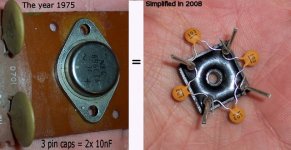
On an unloaded power supply, my voltmeter reads 1v to 2v lower figures after snubbing a bridge rectifier.Dan, snubbing the secondary will not affect rail voltage at all.
Similar to what Mark Houston did here.
But I did it like this, same as Technics circa 1975:
Attachments
Last edited:
Dan, it could be EMI fooling the meter. I've anguished my meters several times on oscillating amps and so on. Try hooking the meter up with 10k resistors in series with the probes, and a 100n cap or so across the probes.
BTW that's not snubbing, just capacitive bypass or decoupling.
BTW that's not snubbing, just capacitive bypass or decoupling.
Last edited:
Those rectifiers must be emitting TONS of EMI. I would not trust a meter here. Even so a volt or so rail difference should not matter; One should not expect the mains voltage to be exact and the Technics designers would not have made this mistake.
Perhaps without the bypass the rectifier area resonances were at high enough frequencies to stomp the AGC? In any case the bypass won't remove resonances but it will lower their frequency and localize the diode snap to a smaller area.
Perhaps without the bypass the rectifier area resonances were at high enough frequencies to stomp the AGC? In any case the bypass won't remove resonances but it will lower their frequency and localize the diode snap to a smaller area.
Last edited:
Dan, are you measuring AC voltage or DC voltage? It should not change DC voltage.
There is a fun and easy way to adjust the snubber I just used. Take an inductor and probe it with the oscilloscope. Use a trimmer or pot as a series resistor; it may resonate with your scope and you'll need the trimmer to tune out the resonance (parallel trimmer should work better, but I didn't try it). I used a 50k pot. Put the magnet near a CRT monitor or something that make RF pulse noise and adjust the pot so that there is no resonance shown on the scope (make sure the resonance is higher in frequency than the resonance you are trying to measure, or it will mask the measurement). Put the inductor near the trafo. You'll see the integral of the rectifier charging pulses. There will be slanted sections between flat sections. The slanted/distorted sections are the charging pulses. There will be a bounce or resonance as they snap to the flat sections. Adjust the snubber for the most benign bounce behavior. My 3.3u snubber cap is still too small; I cannot make the R small enough without creating another 2KHz resonance. But a 2KHz resonance is more tolerable than a 14KHz resonance which causes sibilance and disrupted imaging and general harshness.
There is a fun and easy way to adjust the snubber I just used. Take an inductor and probe it with the oscilloscope. Use a trimmer or pot as a series resistor; it may resonate with your scope and you'll need the trimmer to tune out the resonance (parallel trimmer should work better, but I didn't try it). I used a 50k pot. Put the magnet near a CRT monitor or something that make RF pulse noise and adjust the pot so that there is no resonance shown on the scope (make sure the resonance is higher in frequency than the resonance you are trying to measure, or it will mask the measurement). Put the inductor near the trafo. You'll see the integral of the rectifier charging pulses. There will be slanted sections between flat sections. The slanted/distorted sections are the charging pulses. There will be a bounce or resonance as they snap to the flat sections. Adjust the snubber for the most benign bounce behavior. My 3.3u snubber cap is still too small; I cannot make the R small enough without creating another 2KHz resonance. But a 2KHz resonance is more tolerable than a 14KHz resonance which causes sibilance and disrupted imaging and general harshness.
- Status
- This old topic is closed. If you want to reopen this topic, contact a moderator using the "Report Post" button.
- Home
- Amplifiers
- Chip Amps
- Optimizing TDA7294 Output