Maybe we could use lower compensation with more gain
http://jimmy.thomas.free.fr/temp/TDA7293/TDA7293-MESURES.pdf
page 8 : 6X gain is stable without compensation
so it could be completely stable with a small compensation
http://jimmy.thomas.free.fr/temp/TDA7293/TDA7293-MESURES.pdf
page 8 : 6X gain is stable without compensation
so it could be completely stable with a small compensation
Last edited:
No, you are right about gain...also note heavy RC compensation on input to make it stable for such a low gain.
I am wondering at the purpose of such a design ?
presumably low noise ?
3 mhz oscillation at 3.2x gain!
Last edited:
http://www.diyaudio.com/forums/atta...0-optimizing-tda7294-output-tda7293-hi-fi.gif
Hi Daniel,
what do you recommend as other changes in this diagram ?
Mute and STBY are optimal ?
In fact, what is the best TDA7293 diagram uncompromising ?
Thanks
I do have a Parallel TDA7293 thread that produces an excellent 90 Watts for your very loud party.
However, there's no such thing as uncompromising with audio although there IS the possibility to fine tune per your particular usage.
If you want a lesser amount of compromise, see the SSA discrete amplifier projects (some odd 40 watts of high end sound--quite good!).
Or, if you want a loud blast of rather authentic concert sound (with a palatable tone to make that useful), see my mods in the TDA7293 Parallel thread. In either case, using them for what they're made for, yields best results.
Sorry, not yet. I had another amp that needed my attention. I will try to get to it this week. As good as the one channel sounds this looks promising.
Blessings, Terry
Alternatively,
one may cut the gain and use the TDA7294 with a 13.5+13.5vac through 15vac+15vac transformer (anywhere in that range) and a 1u input cap. The low voltage allows decreasing the gain (and you should). Sometimes even the ill datasheet component values could even work. At the voltages that I mentioned 2k7+60k is "in the ballpark" for an optimal gain divider. One can use 220u cap (plus a suitable and/or crazy bypass) for inverting input coupler, and use 220u (or parallel 220u) for power decoupling. In this case of undervolting, you get the flea power mod, which is excellent unless you wanted to break ears and plaster. As described, it should run cool and stable and image very well.
By description, it seems that you have gotten some fake TDA7294's (the real thing hasn't been seen in many years, so that's not a surprise).
Version 6 ("V6") TDA7293 = old TDA7294 with advanced feature set enabled. Version 7 ("V7") TDA7293 = real TDA7293. Version 6 ("V6") TDA7294 = TDA2030A (lower voltage and lower gain, simultaneously). SO, if it behaves poorly, the power voltage (and gain) is probably far too high for what it actually is.
If your TDA7294 was made in March and version 6, then it is surely a fake, meaning that your power voltage is probably too high for the NEC UPC core (which is delightful, but is a low voltage piece).
Last edited:
TDA7294 and TDA7293 printed with "V6" and "MAR" is highest probability of a fake. However, there are some authentic chips with that same marking and there's no way to tell by visual appearance. TDA7293's are easier to validate by the clip indicator pin, the predrive output and see if they work flawlessly in parallel without ballast. TDA7294's can't be checked any of those ways.So V6 TDA7293 not good as V7 ?
TDA7294 printed with an entirely numeric code and "SINGAPORE" is probably authentic (and old stock, made carefully, not last week).
Last edited:
got another fake!
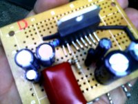
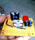
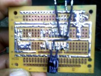
 made this , with fbstring : 68k - 2k2-100u100u047u ; 1uf input cap, 47uf bootstrap, 220uf power cap and 38 V rails unloaded, i tested with lamps in series it was ok then without...
it just made a tiny snap, like a match or something... and died!
its the second with 7293
made this , with fbstring : 68k - 2k2-100u100u047u ; 1uf input cap, 47uf bootstrap, 220uf power cap and 38 V rails unloaded, i tested with lamps in series it was ok then without... it just made a tiny snap, like a match or something... and died!its the second with 7293
Attachments
Hi,
I am new to this chipset TDA7294, I am thinking of using this chipset connected in bridge mode to give me about 150W/channel. I would be using this amp. to drive just the woofer, whose impedance is between 4-8ohms., and below 1Khz.
Those who have experience in this area I welcome a response, also if possible recommend me an off-the-self Ebay kit, I prefer not to design and build it from scratch.
Not recommended to drive bridged into a drive unit going below 8R. That's because each side 'sees' half the total impedance and going below 4R is discouraged. I'd recommend you find a TDA7293 board where the chips are paralleled. Bridged/paralleled with 4 * TDA7293 would work a treat and ensure you didn't have to work hard at optimizing the heatsinking to achieve 150W. You'll still have some power in reserve.
Look for something similar to this :
TDA7293 BTL Parallel 350W Mono Power Amp Borad Kit New | eBay
Look for something similar to this :
TDA7293 BTL Parallel 350W Mono Power Amp Borad Kit New | eBay
Not recommended to drive bridged into a drive unit going below 8R. That's because each side 'sees' half the total impedance and going below 4R is discouraged. I'd recommend you find a TDA7293 board where the chips are paralleled. Bridged/paralleled with 4 * TDA7293 would work a treat and ensure you didn't have to work hard at optimizing the heatsinking to achieve 150W. You'll still have some power in reserve.
Look for something similar to this :
TDA7293 BTL Parallel 350W Mono Power Amp Borad Kit New | eBay
Thanks for the caution I overlooked the susceptibility of bridge amp. to low load, i.e <4 ohms.
These chips explode immediately if the bootstrap cap is backwards or a bad cap. Might want to give that thing a quick checkup before powering on. Or the easy way--a 33u Nichicon ES, which is good quality and never backwards.
i had one board with a sam young (yellow) bootstrap cap. the cap was installed correctly. it exploded (sizzling sound, then BOOM) after a few minutes use at +/-25VDC rails. replaced it with a panasonic FC. the amp resumed working for a few days and then failed entirely. so my takeaway from that is in the event of a bootstrap cap failure one may expect to experience immediate chip failure as Daniel did or a chip failure later as happened to me.
A different possibility is a faltered/failed mute diode, which would then allow the large signal to turn on before the small signal for instant exploded amp.i had one board with a sam young (yellow) bootstrap cap. the cap was installed correctly. it exploded (sizzling sound, then BOOM) after a few minutes use at +/-25VDC rails. replaced it with a panasonic FC. the amp resumed working for a few days and then failed entirely. so my takeaway from that is in the event of a bootstrap cap failure one may expect to experience immediate chip failure as Daniel did or a chip failure later as happened to me.
Solutions include:
Replace 1N4148 (0.2A) with 1N4007 (1A), since the stronger part is approximately 5 times less likely to blow up the amp.
That's like factory specs, except not crash. OR
Short the mute diode (replace that diode with a solid copper wire) and remove the mute cap. . . leaving the mute powered with a simple 10k resistor (just one part--that other junk was not needed).
Mine are simple like this, highly reliable.OR
Use a far smaller cap for the mute (theoretically, that will do it, but I have not tried that particular option, but anyway not larger than 2uF mute cap).
Generally, if you want an op-amp to accept lower gain, using Inverting mode is advisable. Also lower voltage use can help somewhat. And a good quality power circuit is also helpful, although the layout is rather difficult to get the 220uF caps extremely close to pins 7 and 8. . . unless one started a new layout that way firstly, did the small signal next, and then worked everything else in afterwards.UltimateX86 said:I found B&W DM605 service manual using TDA7294 as inverting mode with only 4X GAIN !
Even doing all of those things done right, 4X gain is too low without supplementary compensation.
Inverting mode T-net possibly could be done, which doesn't cost as much board space as an RC collection.
P.S.
Real TDA7294's have either "SINGAPORE" or "TDA7293" printed on the chip.
Last edited:
A different possibility is a faltered/failed mute diode, which would then allow the large signal to turn on before the small signal for instant exploded amp.
Solutions include:
Replace 1N4148 (0.2A) with 1N4007 (1A), since the stronger part is approximately 5 times less likely to blow up the amp.
OR
Short the mute diode (replace that diode with a solid copper wire) and remove the mute cap. . . leaving the mute powered with a simple 10k resistor (just one part--that other junk was not needed).
OR
Use a far smaller cap for the mute (theoretically, that will do it, but I have not tried that particular option, but anyway not larger than 2uF mute cap).
i had not used the mute cap or diode so they were not at fault in my particular case
BTW the other boards have been fine whether inverting or noninverting.
inverting did have lower distortion and tolerated lower gains, in my particular setup. YMMV.
Last edited:
Thanks Steve! That is interesting. I wish I had learned more about it. Most especially specific schematic examples (hint, hint).. . .inverting did have lower distortion and tolerated lower gains, in my particular setup. YMMV.
to me it is a great-sounding amp (with TDA7293 or LM3886) and works fine solo, bridge, parallel, or BPA.Thanks Steve! That is interesting. I wish I had learned more about it. Most especially specific schematic examples (hint, hint).
i used 1% Dale CF RN60s because to me there are fewer weird artifacts than reasonably-priced MF parts.
the pot is there to zero out the offset (to well under 1mv)
i posted the schematic in the P2P inverting thread here:
http://www.diyaudio.com/forums/chip-amps/264015-tda7293-inverting-t-network-fb-point-point.html
it uses a t-net for the NFB but the results are the same with your R values and no t-net, it just requires a bigger input cap (or buffer) that way.
so it becomes like this:
R1 replaced with a wire
R2 omit
R3 27k
R4 50k cermet multiturn pot
R5 1k
C1 BIG || nice poly
the t-net is nice because you can use a nice poly at C1 (i used a 3.3 uf panasonic)
it would be great to have someone else build it to confirm repeatability of my results--which is the acid test IMHO.
Last edited:
- Status
- This old topic is closed. If you want to reopen this topic, contact a moderator using the "Report Post" button.
- Home
- Amplifiers
- Chip Amps
- Optimizing TDA7294 Output