No...Chennai = Tamil Nadu = Madras = Indiais that right?
3RS = India?
Ashok only confirms 3RS in his profile.
That neither confirms nor denies my answer to your irrelevant question.
.........irrelevant question.
What's irrelevant aboutchip was bought locally. All parts were bought locally.
I don't know where you local is.
Does anyone?
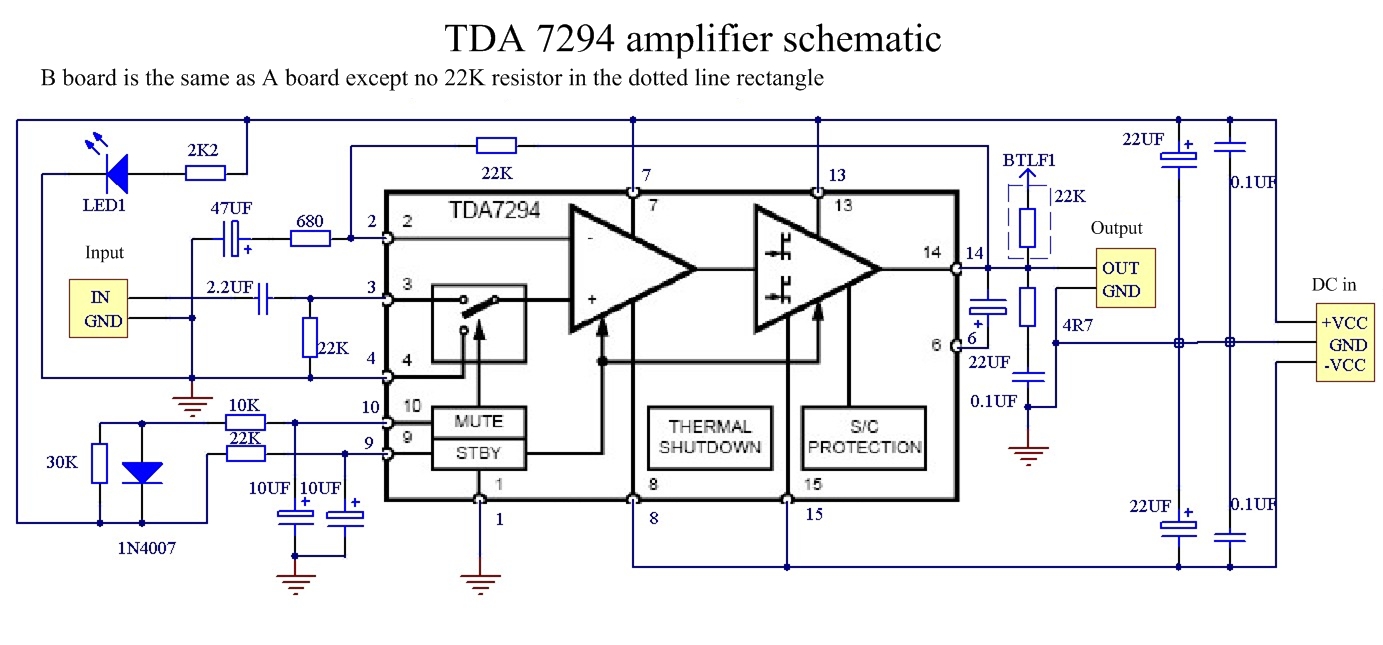
OK, so I bought this kit.
TDA7294 Monobtl Stereo 100W Amplifier Kit Two Separarate Boards | eBay
It came in yesterday and I soldered it up. One channel works and the other doesn't. I see oscillation on the pins 6 and 14 on the bad channel and it will not pass a sine wave. I checked voltages on the pins and they all match channel to channel except for pin#10. That one is labeled MUTE. On the channel that works I see 24.90v and one the non working channel I see 28.80v. Is this a sign that the chip is bad? I checked the resistors and they are what they should be and there are not shorts.
Thanks, Terry
Attachments
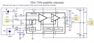
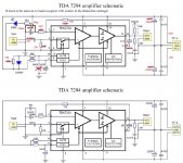
Gosh, that thing is so very slow that oscillation is unlikely by design, so unless it is using the dreadful datasheet schematic (as usually not suitable for any particular chip but rather generic to demonstrate problems), then the oscillation is probably caused by a broken chip, which could indeed easily be broken by using the datasheet sample schematic. Even the worst TDA is capable of better than that. That was a bit cruel! I have previously posted many alternatives. Those are not perfect but ALL of them work better than the datasheet generic sample schematic. That thing should come with a warning. The text is great but all of the images are bankrupt.
This thing is goshawful bad!
That's just about how to blow it up or at least maximize distortion. And the component values, well I only wish I could get that drunk just to see what it is like. Were they trippin on acid? I haven't tried that yet. Anyway, that schema will harm your chip or at least guarantee that it won't replay music acceptably. I've seen worse than that, but not very much worse. They've assured that both the bootstrap and stability will fail. And that's actually hard to do! Oh so very bad!
Last edited:
YepCan you post some photo's of your build.
Not shown, but probably useful for the lower quality chips is 33u bootstrap cap, 100k feedback resistor, 2k7 feedback-shunt resistor, 220u feedback-shunt coupling cap, 1u input coupling cap, omit the cap from the mute circuit. The power caps shown are 220u. It is useful to mount both of the gain divider resistors as close as possible to the voltage amp, without using the roundabout PCB traces.
The thing shown in the photo is a TDA7293 specific parallel amp which does not cost more than a poorly TDA7294 ebay amp kit.
The power circuit shown, works for either.
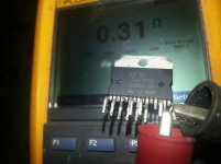
My First account of bad experience with tda 7294.
It was purchased Locally in December, Used for Subwoofer with 2sc5200/1943 boosters.
It sounded pretty powerful and satisfactory with 36-0-36 volts dc input and a generous heatsink.A day of operation would make it warm(I can keep my hands on Heatsink without any casuality. viz50-60 degree celcius)
Approximately after 5 weeks there was only a loud buzz in woofer .I desoldered the chip and found this, output and pin 15 has shorted
What could be the reason?
Regards
Attachments
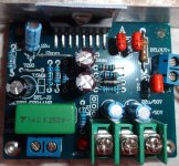
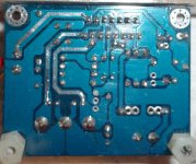
Hi Mark,Can you post some photo's of your build.
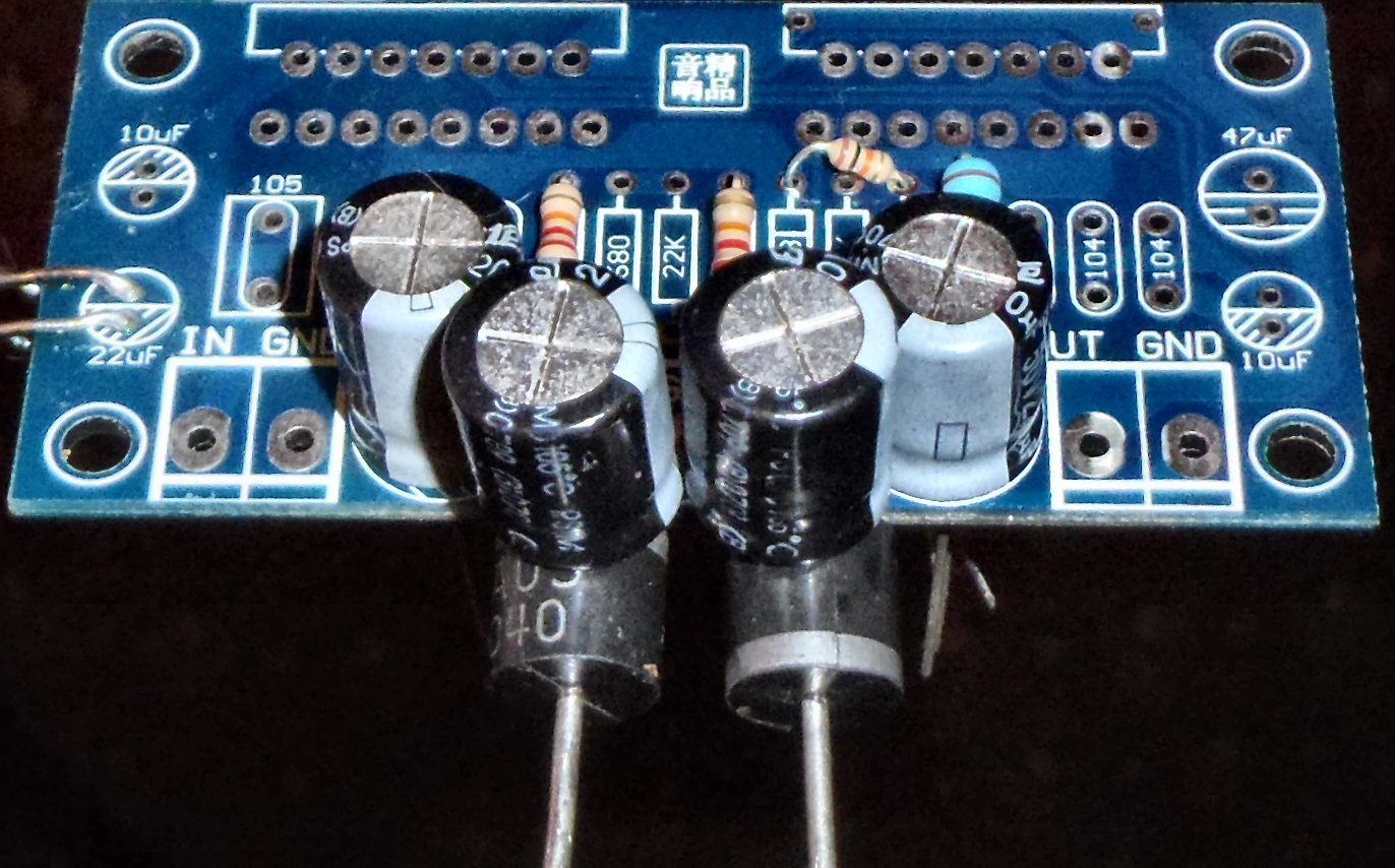
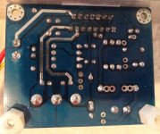
Here you go. First two are right channel and second two are left channel.
Stanton is sending a replacement chip.
Hi Daniel,
It is clear that you don't like this chip. Do you have any helpful advice other than how "dreadful" they are?
Attachments
Actually, my favorite amp uses the TDA7294 chip (an older production that is very much like a currently produced TDA7293).Hi Daniel, It is clear that you don't like this chip. Do you have any helpful advice other than how "dreadful" they are?
And the answer to your question is yes.
I tested the following component values with the new chip:
33u bootstrap cap, 100k feedback resistor, 2k7 feedback-shunt resistor, 220u feedback-shunt coupling cap (in parallel with a 10n polyester bypass cap), 1u input coupling cap, omit the cap from the mute circuit, and the power caps are 220u (Panasonic "tallboy" version, 50v. Give those a push--they'll sort of fit).
And, put the feedback resistor and feedback shunt resistor on directly, without using the PCB traces. The feedback resistor, 100k goes directly across the chip from inverting input to speaker output. The feedback-shunt resistor, 2.7k (a high quality part would be good), goes directly from inverting input to nfb-shunt coupling cap for which you can use a lower voltage 220u cap so that it fits easily. Have a look under the board--there is room for those two resistors and it will not be difficult.
The above component values are with the normal power supply voltage; however, if you happen to under-volt it severely, then you can do almost identical to the above example, except 56k feedback resistor for lower gain (which is made more easily doable when also much lower voltage). In this latter case, the new model chip works extremely well for a mini system. I put one in my table radio and it images really well.
Edit: The little blue block connectors need desoldered and removed from input and output. The slippery connection is not suitable at output because it could explode the amplifier.
Last edited:
With the +/- 25v, (which is good news actually) I had to guess a bit. This (attached) is probably in the ballpark, but you could make the input load (shown 27k) and feedback resistor (shown 75k) a standard resistor value step either higher or lower for tone versus imaging purposes. In either case, lower figures will image better and probably result in an impractical baleful tone, but higher figures will have poorer imaging and a far more pleasant tone. It could be tweaked somewhat. I have attempted to hit the middle ground, but that is subjective.
Basically, from this point (attached) here's a couple of adjustments:
For better imaging at slight cost to tone, change the 27k input load to 22k so you don't get bored.
Or for better tone at slight cost to imaging, change the 75k feedback resistor to a higher figure.
That can fine tune it a bit.
Basically, from this point (attached) here's a couple of adjustments:
For better imaging at slight cost to tone, change the 27k input load to 22k so you don't get bored.
Or for better tone at slight cost to imaging, change the 75k feedback resistor to a higher figure.
That can fine tune it a bit.
Attachments
Last edited:
Hi Daniel,
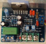
I am attaching a pic with the changes I think you are suggesting. Can I leave the LED and 1n4007? Do you see any other mistakes I have made? My plan, once the replacement chip gets here, is to make the changes you suggest to one board only so I can test them against each other and see what differences I see and hear. Thanks for your efforts here.
Blessings, Terry
Attachments
Hi Still4given,
Try re-soldering the pins of chip on the left channel. They don't look so good in the photo.
What are the 13mm wires for? I saw some finished boards and they were not installed.
Hi Mark, Thanks for looking. The solder is good. It looks small in the photo because I didn't trim the leads. I re-flowed all of it when things didn't work the first time. The wires are just there so I could hook up my scope. I have not hooked up a speaker. As I said, it will not pass a sine wave. All pins agree except for pin#10. I also checked continuity between each pin and the component at the opposite end of each trace. Not sure what more I can do besides change the chip.
Thanks, Terry
It looks like you didn't make any mistakes.Hi Daniel,
I am attaching a pic with the changes I think you are suggesting. Can I leave the LED and 1n4007? Do you see any other mistakes I have made? My plan, once the replacement chip gets here, is to make the changes you suggest to one board only so I can test them against each other and see what differences I see and hear. Thanks for your efforts here.
Blessings, Terry
When not using the mute cap then don't use the mute diode.
Likewise, it is a small signal voltage amplifier area and that is not a useful spot for extra leds to run (except if we needed to drain the decoupler caps, but ours are so small that they don't need and shouldn't use extra drainers).
It would be great if you installed the LED's on both rails of and onto your power supply board. Led's are really very useful on the power supply board for a variety of practical functions. So, I suggest to relocate them to, one LED on V+ on the power board and one LED on V- on the power board.
We really do want to streamline the voltage amplifier area, because chip amplifiers apply gain to everything on the entire amplifier board. Yes, all of the traces will sound and all of the caps are signal caps.
I think that you should leave the input load at 22k and only change it to a higher figure if needed to defeat hard sound; and, so, do that part last.
Last edited:
Hi Mark, Thanks for looking. The solder is good. It looks small in the photo because I didn't trim the leads. I re-flowed all of it when things didn't work the first time. The wires are just there so I could hook up my scope. I have not hooked up a speaker. As I said, it will not pass a sine wave. All pins agree except for pin#10. I also checked continuity between each pin and the component at the opposite end of each trace. Not sure what more I can do besides change the chip.
Thanks, Terry
Pin 10? Mute.
Try this: Remove the cap and short the diode with a wire.
Now the mute is powered by only a simple 10k, and that should be just fine.
Ah, also double check to make sure that this resistor has voltage present.
Last edited:
- Status
- This old topic is closed. If you want to reopen this topic, contact a moderator using the "Report Post" button.
- Home
- Amplifiers
- Chip Amps
- Optimizing TDA7294 Output