Hello,
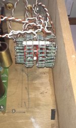
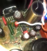
I have changed C13 with Obbligato Gold, before I had EVOX RIFA. The difference is remarkable ! The sound is not more harsh or fatiguing") Il like it There is also more bass and that's good for my system.
Il like it There is also more bass and that's good for my system.
I wonder to use Obbligato also on the tweeter...
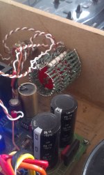
I had some problems to fit the cap, I have employed a wood base under one cap to get up of about 1cm. Later I will maybe fix it with some "mastic" glue to the PCB.
That's said, I've also build the ladder potentiometer, there is not a big difference but the sound is more defined and open.
Now I am waiting for LF 07 I hope there will be enough place to fit it near C13...
I have changed C13 with Obbligato Gold, before I had EVOX RIFA. The difference is remarkable ! The sound is not more harsh or fatiguing
Il like it There is also more bass and that's good for my system.I wonder to use Obbligato also on the tweeter...
I had some problems to fit the cap, I have employed a wood base under one cap to get up of about 1cm. Later I will maybe fix it with some "mastic" glue to the PCB.
That's said, I've also build the ladder potentiometer, there is not a big difference but the sound is more defined and open.
Now I am waiting for LF 07
I hope there will be enough place to fit it near C13...Attachments
Hi Marco - LF07 will fit comfortably in the DIP8 socket for the LM318 (if you've socketed it). Otherwise, just add a DIP8 socket when you remove the LM318.
Evox/Rifa PHE426 has been observed to sound harsh at C13 long ago, by Dario and others. However, there are some metallized MKP caps which are not too harsh at C13 - Arcotronics R75 (?) and EFC/Wesco SP1213-TX are two examples of relatively inexpensive MKP caps which are acceptably good at C13, IMHO.
(If the red Audiophiler MKP caps from EBay China have been tried by anybody here, please provide your audible impressions.)
I must have been sleeping. Missed the announcement/details on the LF07 - I think???
Hi Bob - the LF07 is similar to the LF01, using an LM318 but with a different Class-A biased output stage (which I call the Diamond-like buffer) with lower stage current than the LF01. The LF07 is also more compact due to the use of SMD parts. The audible sonics are similar in both cases - there may be minor audible differences if the rest of the setup (source, speaker, interconnects, etc.) is more resolving than mine.
Thanks, sounds interesting. We'll be following Kreisky's progress and reports. After the recent recovery of the v1.3s, the LF01s were put back in. They still sound smooth, clean and stately Hope to transplant the set to a metal chassis later this summer.
Hope to transplant the set to a metal chassis later this summer.Attachments
Last edited:
Wish I could take the credit, but those are from CPU heatsinks for Intel Server boards. I bought a bunch on eBay for a render farm I started years ago. Every time I post a photo with them I get complements and inquires - should have bought all they had as they are perfect for chip based amps.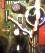
Shouldn't be a problem. It's a tight fit on mine also, but a couple extensions work just fine. Hopefully, you left a little extra lead on the bottom of the big gold cap.
Yes Bob, I have some lead left also under the PCB
Thank you for the pics!
Hello guys, I hope everyone is in good health and all. This is my first post on diyaudio
Anyway, 2 months ago I bought Mauro Penasa Rev C monoblock boards (pair) locally in my country, because at that moment I was not quite satisfied listening to my Rotel RB1552 Power Amp. This was going to be my first diy project. I had no knowledge of reading the components value nor I was able to solder them. So I read a lot on the web and also practiced soldering on my unused P3 mobo.
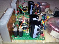
After I had a lot practice and confident, I populated the boards using LM3886Ts, MUR820s, Takman 1/2 watt resistors mostly for 1/4watt, they don't have 1/4watt locally, Black Gate F and Elna Silmics caps, Vishay MKP caps and Talema toroidal transformer Primary 225v, Secondary 2x25v. When I switched it on, both relays triggered. Voila, the amp works, no hum no noise It sounds so much better than my recent amp - My wife also loves it.
It has been running for more than 100 hours, but the heatsinks becomes warm after 1/2 hour playing music. I thought I had to install bigger heatsinks, at the moment I use 15cm x 8cm x 2cm (2mm), so for playing for more than one hour, I use a portable fan to blow the amp. The range voltage in my home is about 220-240v. I ever tested AC value from the toroid with my multimeter, it showed 27.12, 27.52, 27.79 secondary. But I don't know how to measure DC voltage of the amp.
Yesterday, one of the channel started screeching after playing about 10secs. I thought it was because I moved the amp into a wood box, so I rechecked for loose connections, but nothing. When I switched it on, both relays triggered normally, when I play music, it sounds from both channels, but one channel started screeching again after few secs. It stops when I stop the music. I observed the one with the problem, heatsink is getting hot very quickly than the other.
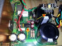
Guys, please help me debugging the problem. Here I attached the board photo. I don't know what version it is. Thank you.
Anyway, 2 months ago I bought Mauro Penasa Rev C monoblock boards (pair) locally in my country, because at that moment I was not quite satisfied listening to my Rotel RB1552 Power Amp. This was going to be my first diy project. I had no knowledge of reading the components value nor I was able to solder them. So I read a lot on the web and also practiced soldering on my unused P3 mobo.
After I had a lot practice and confident, I populated the boards using LM3886Ts, MUR820s, Takman 1/2 watt resistors mostly for 1/4watt, they don't have 1/4watt locally, Black Gate F and Elna Silmics caps, Vishay MKP caps and Talema toroidal transformer Primary 225v, Secondary 2x25v. When I switched it on, both relays triggered. Voila, the amp works, no hum no noise
It sounds so much better than my recent amp - My wife also loves it.It has been running for more than 100 hours, but the heatsinks becomes warm after 1/2 hour playing music. I thought I had to install bigger heatsinks, at the moment I use 15cm x 8cm x 2cm (2mm), so for playing for more than one hour, I use a portable fan to blow the amp. The range voltage in my home is about 220-240v. I ever tested AC value from the toroid with my multimeter, it showed 27.12, 27.52, 27.79 secondary. But I don't know how to measure DC voltage of the amp.
Yesterday, one of the channel started screeching after playing about 10secs. I thought it was because I moved the amp into a wood box, so I rechecked for loose connections, but nothing. When I switched it on, both relays triggered normally, when I play music, it sounds from both channels, but one channel started screeching again after few secs. It stops when I stop the music. I observed the one with the problem, heatsink is getting hot very quickly than the other.
Guys, please help me debugging the problem. Here I attached the board photo. I don't know what version it is. Thank you.
An externally hosted image should be here but it was not working when we last tested it.
"Screech" may be oscillation.
Do you have access to an oscilloscope?
Is the Output Zobel still working?
Is the RF attenuation still connected?
Is there a stable DC on the output? How many mVdc and how much does it move as the amp warms up from COLD to WARM to HOT?
Measuring DC.
set your DMM to 200Vdc.
attach black probe to Main Audio ground.
Probe with the red to +ve rail, then probe to the -ve rail.
move the black probe to -ve rail. Red probe to +ve.
This final answer should exactly equal the sum of the two earlier +ve & -ve readings.
Keep the 200Vdc setting and measure the output offset. Black is connected to Main Audio Ground.
Red to the output. If the reading is well below 20Vdc, then rest to 20Vdc and remeasure. If the reading is well below 2Vdc, then rest to 2Vdc and remeasure. If the reading is well below 200mVdc, then reset to 200mVdc and remeasure.
expect a reading between -10mVdc and +10mVdc. Any higher and you have assembled it wrongly.
Last edited:
"Screech" may be oscillation.
Do you have access to an oscilloscope?
Is the Output Zobel still working?
Is the RF attenuation still connected?
Is there a stable DC on the output? How many mVdc and how much does it move as the amp warms up from COLD to WARM to HOT?
Measuring DC.
set your DMM to 200Vdc.
attach black probe to Main Audio ground.
Probe with the red to +ve rail, then probe to the -ve rail.
move the black probe to -ve rail. Red probe to +ve.
This final answer should exactly equal the sum of the two earlier +ve & -ve readings.
Keep the 200Vdc setting and measure the output offset. Black is connected to Main Audio Ground.
Red to the output. If the reading is well below 20Vdc, then rest to 20Vdc and remeasure. If the reading is well below 2Vdc, then rest to 2Vdc and remeasure. If the reading is well below 200mVdc, then reset to 200mVdc and remeasure.
expect a reading between -10mVdc and +10mVdc. Any higher and you have assembled it wrongly.
Hi Andrew, thanks for your response. I don't have an access to an oscilloscope. I don't understand what output zobel and RF attenuation are, sorry
Today I measured the toroid output AC voltage, showing at 27.36 and 27.36 secondary respectively providing the AC input from the wall showing at 232v. I measured DC offset of output reading -3mVdc and -2.2mVdc without playing music, (put MM's red probe on + output and black probe on - output).BTW, when I switch the amp on without the music played, the heatsink of channel with the screeching problem is just as cool as the other. But when I play music just about 10secs normally, the channel with the problem screeches again and the heatsink getting warm to hot very quickly, so I don't have gut to measure the dc output but turn it off directly.
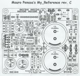
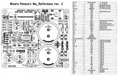
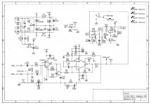
Here I attach a clearer schematic of the pcb.
(where is the main audio ground
)Attachments
Don't fit speakers while you are still in the testing phase. Never !
Output offset is measured with the input shorted and the output open, but with the Zobel properly connected.
Post the sch and we can show the Zobel components. Then you can measure.
R11 may be the Zobel resistor, but I can't identify the C from that layout.
Output offset is measured with the input shorted and the output open, but with the Zobel properly connected.
Post the sch and we can show the Zobel components. Then you can measure.
R11 may be the Zobel resistor, but I can't identify the C from that layout.
Last edited:
Here I attached the board photo. I don't know what version it is. Thank you.
It's an unauthorized EBay copy of my Rev C V1.4 layout, without attribution and some minor layout changes. However, the silver lining is that it should probably work fine if you stick to any standard Rev C BoM.
There's no Zobel on any Rev C, AFAIK, and it's not needed.
28-0-28 is a bit too high for a MyRef, and it's likely that the LM3886TF SPiKe protection will kick in unless the heatsink is really good. If you want it to run cool and without distortion, the AC voltage of the trafo should be 24-0-24 or lower.
Also check carefully that the LM3886 and LM318 are authentic and not counterfeit (there are counterfeits of the LM3886, and there are aftermarket LM318 clones which aren't exactly equivalent to the original NatSemi version. If in doubt, go with the original NatSemi version).
You may also want to change R14 to 180 ohms, and R21 to 100k - it allows more reliable operation with most 24V sugarcube relays when running with a 24-0-24 trafo.
Last edited:
Back in January varun21 had the same problems with a different board. He could only get it to work by replacing the LM318 with a TL071.
http://www.diyaudio.com/forums/chip-amps/54571-my-audiophile-lm3886-approach-426.html#post3769586
http://www.diyaudio.com/forums/chip-amps/54571-my-audiophile-lm3886-approach-426.html#post3769586
I have re-flowed the solder, the problem still persists.
Hi linuxguru, I apologize I wasn't aware that I purchased unauthorised copy of your Rev C 1.4 layout. I got it from local forum. I am a newbie in diy audio world and just have learnt later they are many many counterfeits products out there as just one my best friend told me most of electronic components sold locally are 95% counterfeits and fakes from China. That's why I bought boutique components from trusted and recommended stores by local diy-ers and later I bought some caps from hifi******ive uk.
I bought the LM3886T and LM3886TF as spare and LM318N from someone of local forum who showed me the proof of purchase was made from mo***r.
A current heatsink installed dimension is 15cm(L) x 8cm(H) x 2cm(W) (thickness is 2mm). So far I am using a portable fan to cool down the heatsink when playing more than 1 hour. A new set of bigger heatsink (15cm(L) x 8cm(H) x 4.5cm(W) (thickness is 6mm)) is coming.
My rated AC from the wall shows 220v-240v. I am thinking of getting voltage stabilizer set the AC to 220v, so my Talema Toroid rated at 230VAC primary and 2x25VAC secondary will be stepped down to 220VAC and around 2x24/25VAC? Or should I buy a new trafo rated 2x24VAC secondary. BTW, I am using 8 ohm 2 way speakers.
I will also try your recommendation to install a new R14 and R21. Thank you
Let's continue, I am willing to learn although I am a slow learner
Okay, thanks Mark. Will also try the solution
It's an unauthorized EBay copy of my Rev C V1.4 layout, without attribution and some minor layout changes. However, the silver lining is that it should probably work fine if you stick to any standard Rev C BoM.
There's no Zobel on any Rev C, AFAIK, and it's not needed.
28-0-28 is a bit too high for a MyRef, and it's likely that the LM3886TF SPiKe protection will kick in unless the heatsink is really good. If you want it to run cool and without distortion, the AC voltage of the trafo should be 24-0-24 or lower.
Also check carefully that the LM3886 and LM318 are authentic and not counterfeit (there are counterfeits of the LM3886, and there are aftermarket LM318 clones which aren't exactly equivalent to the original NatSemi version. If in doubt, go with the original NatSemi version).
You may also want to change R14 to 180 ohms, and R21 to 100k - it allows more reliable operation with most 24V sugarcube relays when running with a 24-0-24 trafo.
Hi linuxguru, I apologize I wasn't aware that I purchased unauthorised copy of your Rev C 1.4 layout. I got it from local forum. I am a newbie in diy audio world and just have learnt later they are many many counterfeits products out there as just one my best friend told me most of electronic components sold locally are 95% counterfeits and fakes from China
. That's why I bought boutique components from trusted and recommended stores by local diy-ers and later I bought some caps from hifi******ive uk.I bought the LM3886T and LM3886TF as spare and LM318N from someone of local forum who showed me the proof of purchase was made from mo***r.
A current heatsink installed dimension is 15cm(L) x 8cm(H) x 2cm(W) (thickness is 2mm). So far I am using a portable fan to cool down the heatsink when playing more than 1 hour. A new set of bigger heatsink (15cm(L) x 8cm(H) x 4.5cm(W) (thickness is 6mm)) is coming.
My rated AC from the wall shows 220v-240v. I am thinking of getting voltage stabilizer set the AC to 220v, so my Talema Toroid rated at 230VAC primary and 2x25VAC secondary will be stepped down to 220VAC and around 2x24/25VAC? Or should I buy a new trafo rated 2x24VAC secondary. BTW, I am using 8 ohm 2 way speakers.
I will also try your recommendation to install a new R14 and R21. Thank you
Haha.. That's okay, AndrewMy memory is playing tricks.
Indeed there is no Output Zobel in the My Ref revC
Let's continue, I am willing to learn although I am a slow learner Back in January varun21 had the same problems with a different board. He could only get it to work by replacing the LM318 with a TL071.
http://www.diyaudio.com/forums/chip-amps/54571-my-audiophile-lm3886-approach-426.html#post3769586
Okay, thanks Mark. Will also try the solution
- Home
- Amplifiers
- Chip Amps
- The new "My Ref" Rev C thread