All's well in V1.3 country.
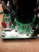
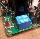
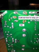
Added bare Cat6 jumpers from top PGND and OGND pads/traces through the hole and soldered them to the relay pins on the bottom. Also put the original caps back in C1 & C2. Works like a charm.
A "tip of the hat" to Siva for supplying a pretty rugged board. Thought I would have lost a lot more pads and vias.")

Mark - You're a Champ!
Added bare Cat6 jumpers from top PGND and OGND pads/traces through the hole and soldered them to the relay pins on the bottom. Also put the original caps back in C1 & C2. Works like a charm.
A "tip of the hat" to Siva for supplying a pretty rugged board. Thought I would have lost a lot more pads and vias.
Mark - You're a Champ!
Attachments
Last edited:
Got a PM that prompts some clarification. I shouldn't have used "jumper" in the earlier post. They are actually just two short tails to connect the traces on top of the board (blind mounting when flush) to the relay pins. The DC protection delay is fully functional.
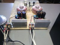
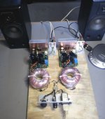
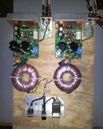
Setting up both V1.3 modules in a dual mono configuration right now and will post it later today.
Setting up both V1.3 modules in a dual mono configuration right now and will post it later today.
Attachments
A "tip of the hat" to Siva for supplying a pretty rugged board. Thought I would have lost a lot more pads and vias.
Thanks, and congratulations on bringing the board back to life! Your persistence definitely seems to have paid off.
Vaguely OT: I know the feeling of elation in reviving a piece of electronics - I thought I had destroyed an old Socket-A mobo yesterday while changing the CPU. The screwdriver slipped while detaching the heatsink clip, and hit/detached an SMD capacitor next to the CPU socket, and the cap flew out of sight somewhere. I hoped that it was just a bypass cap, but alas - the board refused to POST after that. I traced the signal the cap was attached to (CPU_PWRGD) - it turned out to have a 220pF 0603 ceramic on other similar Athlon mobos. Looked around, found a 220pF in 0805 (too big) and a 180pF C0G in 0603 in my SMD parts stash. Carefully soldered the 180pF in place (luckily, the pads were still intact). Carefully re-installed the processor, heatsink and one stick of RAM. Held my breath, crossed fingers and powered-up. Eureka! it went through POST and CPU temperature in the BIOS HW monitor is rock stable at 51c.
Was all the effort to revive an obsolete piece of HW which doesn't fetch more than $20 these days on EBay, really worth it? Maybe not, but I'm still a happy camper. If it didn't POST with the 180pF ceramic, I would have persisted and soldered a 47 pF right next to it in parallel. I didn't need to, though.
(Just as a placeholder reference for those who damage an MSI-7061 KM4M-V or similar motherboard in a similar manner: C4 next to the CPU socket heatsink clip is a 180..220pF 0603 ceramic, and C5 is unpopulated. The board will not POST without C4.)
Last edited:
creation house
Dears, just to say i had the luckiness to meet Dario today. Such a passionate fellow. He explained me his journey to push further the sound of his fab myref. A very enjoyable afternoon. Thanxs Dario and was really nice music the one i heard.
Ciao to all of you guys, apparently in his same boat.
Dears, just to say i had the luckiness to meet Dario today. Such a passionate fellow. He explained me his journey to push further the sound of his fab myref. A very enjoyable afternoon. Thanxs Dario and was really nice music the one i heard.
Ciao to all of you guys, apparently in his same boat.
I gave some attempts time to time. I am good with my solder station but have bad background knowledge of circuits. As similarity its like to read sentences or understand the content of them. But always loved the miracle behind components that when properly assembled play passionate music.
Hello,
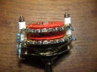
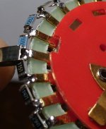
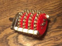
I would like to know what do you think about a stepped ladder pot for My-ref C. Now I have the one in photos, I have made it with SMD 1206, it's 10k and 60db of attenuation.
But... I have also a 4 pole potentiometer that can be used for a stereo ladder pot using an Excel spreadsheet for calculating attenuation values.
So, the question is: is it worth to buy the resistors for a ladder pot instead that shunt pot with SMD ?
It is also difficult to find the resistors values, I've tried to look for Vishay-Dale but I didn't find the right values.
Can I change from 10k to 20k or 30k ? I know it's a silly question, but does the output SPL decrease if I use a 20k instead of 10k ?
... if I don't find Vishay-Dale, witch resistor can I try ? Not more than 1$ each.
thanks!
marco
Attachments
... so I have tried to calculate the resistors values using Stepped Attenuator Resistor String Calculator - Neville Roberts
There is any difference in using 10k or 12k pot with My-ref C or My-ref A ?
I prefer the step progression of 12k, but also the one of the 10k version could be fine for me.
In the 10k version, the impedance changes from 9k4 to 11k2.
In the 12k version, the impedance changes from 11k to 13k.
Is there any reason to prefer either of the two versions ?
Thanks !
Attachments
The impedance seen by the source should not change significantly when you adjust the volume.
A 10k vol pot feeding a 100k amplifier has an impedance of 10k when set to zero volume and drops to ~9k1 when @ maximum volume.
If the vol pot is buffered then the source never sees a change in impedance, it stays at 10k.
A 10k vol pot feeding a 100k amplifier has an impedance of 10k when set to zero volume and drops to ~9k1 when @ maximum volume.
If the vol pot is buffered then the source never sees a change in impedance, it stays at 10k.
The impedance seen by the source should not change significantly when you adjust the volume.
A 10k vol pot feeding a 100k amplifier has an impedance of 10k when set to zero volume and drops to ~9k1 when @ maximum volume.
If the vol pot is buffered then the source never sees a change in impedance, it stays at 10k.
Hi Andrew, thanks for your reply.
I am sorry
for my very insufficient knowledge in electronic, if the 12k ladder pot changes between 11k e 13k... does it mean that the source sees an impedance between 9k9 and 11k5 ?I try the last time to understand otherwise... never mind
In the 12k vol pot, at step 12, we have Rx=12kohm and Ry=1kohm. At step 13, there is Rx=10k and Ry=1kohm.
The source sees Rx + Ry//100kohm, right or not ?
At step 12 we have: 12k + 990ohm.
At step 13: 10k + 990ohm.
If it's right, the source sees between 11k and 13k.
In the 12k vol pot, at step 12, we have Rx=12kohm and Ry=1kohm. At step 13, there is Rx=10k and Ry=1kohm.
The source sees Rx + Ry//100kohm, right or not ?
At step 12 we have: 12k + 990ohm.
At step 13: 10k + 990ohm.
If it's right, the source sees between 11k and 13k.
that shows you do not have 12k vol pot. it is actually 13k
All the steps should be 13k
mmmh... this is not possible because I don't find the right resistors value. I am looking for PRP or Takman.
I have also read a interesting post of yours about pot :
...
If a source can drive a 20k pot properly then there must be something seriously wrong with the source if the sound quality changes audibly by reducing the loading to 14k3.
Personally, I'd choose a 10k pot for Rin=50k. The range of loading seen by the source is 8k3 to 10k.
The 8k3 loading requires an extra 210uA of peak source current (@~2Vac maximum output) compared to driving a 20k load. I don't see that 60uApk (20k to 14k3) causing any problem of "a variable impedance to the source output"
... then, a variable impedance 11k-13k may not cause any problem to the source... ?
- Home
- Amplifiers
- Chip Amps
- The new "My Ref" Rev C thread