
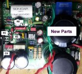
New readings on good board.
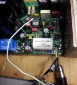
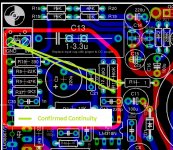
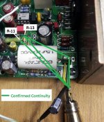
Green wire continuity.
Something interesting - I cranked the Walkman to max on the noise between FM stations. There is a slight signal now on pin 2, ~ 10 - 20% of what appears on pin 3.
Green wire continuity.
Something interesting - I cranked the Walkman to max on the noise between FM stations. There is a slight signal now on pin 2, ~ 10 - 20% of what appears on pin 3.
Attachments
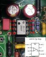
The weak version of the signal appears at LM3886 pin 10. Touching pin 9 cycles the relay. That is the same action that happens when touching the inboard end of R-37. Going back to pin 10 or the signal input terminal produces a very slight pop that sounds like the LM3886 mute is being disengaged. I say that because the relay closes immediately when continuity to pin 9 is broken.
There is definitely a describable release of some sort before the signal reappears at pin 10 and/or the terminal screw.
There is definitely a describable release of some sort before the signal reappears at pin 10 and/or the terminal screw.
Last edited:
LM3886 pin 8 = -5.4 V which should unmute the chip. Maybe pin 7 connection to ground.
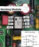
The relays only disconnects the speaker return from the amp GND and doesn't mute the LM3886. The relays de-activating almost confirms that the LM3886 is still working, DC at pin 3.
The problem is the complexity of the circuit. Any of the many feedback resistors can cause similar problems.
R7-R10-C9 / R8-R9-GND / R5-R6 / R3
Bob,
I admire your tenacity it trying to solve this problem. I have one of the my ref C mono blocks that has been nonfunctional for the last two years awaiting some attention. It has 125mV of DC offset. And the other amp is normal at 1.5 mV.
As you are likely to be pulling a number of the resistors I was curious as to how important it is to match the resistors in the "Howland pump". Curious as to whether mismatch could cause amp to not to function properly.
I responded in the myrefC build guide about my experience. Post 73
As it appears you will be removing these resistors would you mind checking to see whether they are as closely matched?
don't know if that will be a factor.
In anticipation of having to tear my board apart it did give me a good reason to purchase a Hakko 808 that I like a lot. I was going to approach the problem in a Shiva the destroyer fashion and not as elegantly as you are doing.
Jack
"To Clarify my experience with 47K, Resistors, R6, R9, and R20
Each mono channel has its own components and they are matched. I wouldn't dump out all the parts for both boards and now have 6 resistors and assume that they are all matched.
For the first board my values were approx
I believe that all of my 47K resistors were all like 46.8 kohm on my Fluke DMM. And so I felt they were all good.
The second packet all the 47K resistors measured 47.0 kohm.
With goal of .1% matching being 47000 +/ - of 47 ohm.
1% of 47,000. being 470 and .1% 47 ohm.
The 22K Resistors, R5,R8, R43. Two of them were the same 22.01 kohm and the the third was within 1% say 21,800
Anyway you get the idea. Two of them are nearly identical. If they all measure the same you are good. Just wanted to give people a heads up as Uriah went to the extra measure to match them and wanted everyone to give this thing he best shot for audio perfection.
Again Uriah many thanks for all your work.
JCon2"
Thanks for the encouragement J. I have some of Uriah's matched Dale resistors but haven't dig them out yet - I will. Gonna do one at a time with generics to see if I can pinpoint the culprit.
I'm using a standard PE station which has served me well but am looking forward to getting a pro system in the near future. Being very careful to use lots of paste flux and solder wick to protect the vias before removal.
More to come.......")
I'm using a standard PE station which has served me well but am looking forward to getting a pro system in the near future. Being very careful to use lots of paste flux and solder wick to protect the vias before removal.
More to come.......
O.K. I think I have replacements for all that you list, so I'll work on those and Siva's suggestions later today.
Bob, there's no need to replace every resistor and capacitor. It's less risky to just measure, inspect and reflow solder on a few pads as necessary. Most passives do not fail in normal operation in this circuit.
There's every possibility of further shorts/opens/pad de-lamination occurring while changing passives that have no measured fault condition.
I agree. I was wondering if a relative mismatch in the Howland section could cause the amp to not work properly. I agree it is very unlikely that the passive parts might fail. I then found your comments of several years ago that the simulations you ran seem to indicate that up to 10% mismatch unlikely to cause problems.
So I'm still cheering Bob on as I have similar problematic amp and don't have quite the patience to put the time into troubleshooting. I appreciate the great pics with the voltages all in one place. Very helpful. Carry on!
Nothing yet 
One at a time - I removed, tested value, cleaned pads, re-installed and verified continuity on R5,6,8,9,10,12. I found two matched sets (2 @ 22K - 2 @ 47K ea.) from Uriah in the stash, but used some extras to replace some resistors. Everything I pulled read correctly and the replacements were done just because I had those extras on hand. I can still place a complete set of the matched parts if needed/suggested.
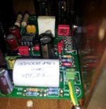
I replaced the chewed-up cap at C4 with the same piece that's installed on my V1.2 builds.
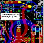
Also verified the appearance of DC on speaker outs at relay closing. Went from 0,0 to 0.03 VDC at power on. I tried to get a continuity reading from PGND entering the relay to the OGND tab. Couldn't get a signal (beep) but did get a current change indication when cycling the power.
Next step is to verify continuity from each cap to it's nearest component. Any particular cap related readings I should grab?
EDIT: Just saw your post Mark. I'll add that to the process.
One at a time - I removed, tested value, cleaned pads, re-installed and verified continuity on R5,6,8,9,10,12. I found two matched sets (2 @ 22K - 2 @ 47K ea.) from Uriah in the stash, but used some extras to replace some resistors. Everything I pulled read correctly and the replacements were done just because I had those extras on hand. I can still place a complete set of the matched parts if needed/suggested.
I replaced the chewed-up cap at C4 with the same piece that's installed on my V1.2 builds.
Also verified the appearance of DC on speaker outs at relay closing. Went from 0,0 to 0.03 VDC at power on. I tried to get a continuity reading from PGND entering the relay to the OGND tab. Couldn't get a signal (beep) but did get a current change indication when cycling the power.
Next step is to verify continuity from each cap to it's nearest component. Any particular cap related readings I should grab?
EDIT: Just saw your post Mark. I'll add that to the process.
Attachments
Last edited:
Sorry, I should explain. The reason I tested for continuity across the relay is that's the only place where major/obvious damage (pulled vias) exists on the board. I inserted 0.015" solder along the side of the pins and let it flow to the topside pad/teace. Was just verifying that it worked now that I can't see the joints after removing those stilts shown in post #1798. I will use the bypass technique though - one less leg to worry about.
Attachments
Last edited:
FANTASTIC - IT"S ALIVE !!! 
Did someone say "Relay" way back there in the beginning? The bypass worked and I don't have a clue if all the other steps aided the solution, but I'm one happy camper today. I did swap out C1 & C2 this morning (one loose top pad but via intact) but still didn't get sound till the bypass was in place.
Still have to determine if the relay, board or protection circuit is flawed, but I think it will be easy from here.
THANKS ALL!! It's been a fun journey.
Did someone say "Relay" way back there in the beginning? The bypass worked and I don't have a clue if all the other steps aided the solution, but I'm one happy camper today.
I did swap out C1 & C2 this morning (one loose top pad but via intact) but still didn't get sound till the bypass was in place.Still have to determine if the relay, board or protection circuit is flawed, but I think it will be easy from here.
THANKS ALL!!
It's been a fun journey.Attachments
Last edited:
- Home
- Amplifiers
- Chip Amps
- The new "My Ref" Rev C thread