I will test your sugestion Andrew. Thank you very much for advice !
Found a useful link: Contact Protection and Arc Suppression Methods for Mechanical Relays
Found a useful link: Contact Protection and Arc Suppression Methods for Mechanical Relays
A cap across the switch is not a suppressor.
You need to buy a switch suppressor.
It is an integrated package containing a resistor+capacitor.
How effective is the RF attenuation that you have fitted to the amplifier and to the Chassis that holds the amplifier?
Wouldn't a flyback diode across the relay contacts do the trick?
if the "pop" is due to a back emf spike from the relay then YES, the back emf diode will help with that.Wouldn't a flyback diode across the relay contacts do the trick?
speed up the opening of relay
There is a way to speed up the opening time of a relay: add in series to the diode of "back emf" a zener diode in order to force the extra opening voltage of the relay coil to stay at the value of the zener voltaege until the energy stored in the winding lapsed. At the opening, a coil becomes a current generator and the voltage at which the discharge occours depends on external device: if there is nothing, the extra voltage can destroy the control transistor. Or, if the the relay is commanded with a han-switch, you can see the spark of opening between the command contacts (not those of the relay, but that hand-commanded). The energy decays much faster with the zener:in fact the energy stored in the coil of the relay is: E = 1/2 LI * I where I is the current through the coil before the opening, L is the inductance of the coil of the relay. At the opening this energy is discharged in time necessary to satisfy: E = V * I * t Where V is the voltage at which the discharge takes place, that is that the zener voltage: if Vzener is high, "t" is small .......
There is a way to speed up the opening time of a relay: add in series to the diode of "back emf" a zener diode in order to force the extra opening voltage of the relay coil to stay at the value of the zener voltaege until the energy stored in the winding lapsed. At the opening, a coil becomes a current generator and the voltage at which the discharge occours depends on external device: if there is nothing, the extra voltage can destroy the control transistor. Or, if the the relay is commanded with a han-switch, you can see the spark of opening between the command contacts (not those of the relay, but that hand-commanded). The energy decays much faster with the zener:in fact the energy stored in the coil of the relay is: E = 1/2 LI * I where I is the current through the coil before the opening, L is the inductance of the coil of the relay. At the opening this energy is discharged in time necessary to satisfy: E = V * I * t Where V is the voltage at which the discharge takes place, that is that the zener voltage: if Vzener is high, "t" is small .......
I forgot to add that the objective of fast opening of the relay is to open the contacts before the supply voltage of the amplifier decreases to too much low values and to avoid the consequent instability: the speakers are disconnected before the power supply voltage drops to values too low.
Hallo, problem here:
I finished populating the boards as follows (C10, C12 and C34 are under the board, and C14 is yet to come, so those are not problems)
Unfortunately I cannot figure out where this cap goes
Anybody so kind to give me help about this..?
I finished populating the boards as follows (C10, C12 and C34 are under the board, and C14 is yet to come, so those are not problems)
An externally hosted image should be here but it was not working when we last tested it.
Unfortunately I cannot figure out where this cap goes
An externally hosted image should be here but it was not working when we last tested it.
Anybody so kind to give me help about this..?
That single wire coming out of C13 MUST be close coupled with the Signal Return wire !!!!!!!
Andrew, you mean that it goes to the 2,2uF (or whatever 1uF or so) input cap, right?
You seem to have moved the input DC blocking cap off board.
The input wires from the RCA/phono socket MUST be a close coupled pair all the way to the +IN and -IN pins of the IC.
You can move the cap, but YOU must maintain the close coupled pair of input wires.
Your pic shows a single wire going into C13 !
Where is the close coupled PAIR of input wires?
You CANNOT have a single input wire. You MUST have a pair of input wires.
Look under your added wire.
The input terminal shows three pads for input wires. They are either 0.2" pin pitch or 0.1" pin pitch. They are almost close coupled. 0.05" pin pitch would be better.
You have destroyed this parameter of the standard PCB !
Last edited:
It would have been better (wrt mechanical integrity) to have C10, C12 and C34 on top of the board. You would have needed a desoldering pump or wick to get the solder out of those pads, though.
The 22nF Wima is most probably C21, which is a bypass for C9. When C9 is a Black Gate, it's not required (and difficult to fit at any rate).
BTW, at the risk of repeating myself ad nauseum - there are non-BG caps that measure and sound very good at C9. Nichicon UD is a good example, I've used them both bypassed and without the C21 bypass, and the sonics are not really distinguishable from a BG.
Ok, removed.
Thanks for the explanation!
Yes Linuxguru, I already checked and posted in the other thread, the 22nF Wilma is bypass for the 220uf cap. Thanks anyway again.
Thanks for the explanation!
Yes Linuxguru, I already checked and posted in the other thread, the 22nF Wilma is bypass for the 220uf cap. Thanks anyway again.
An externally hosted image should be here but it was not working when we last tested it.
How do you plan to run the twisted pair from the input socket to the DC blocking cap, thence a twisted pair from cap to the amp PCB?
If you build exactly as everyone before, then just follow the recipe.
If you plan to modify ANYTHING, then you need to understand what you are doing, why you are doing it and how to achieve the desirable outcome.
Modifying is just as difficult as Designing. A long way from following a recipe.
If you build exactly as everyone before, then just follow the recipe.
If you plan to modify ANYTHING, then you need to understand what you are doing, why you are doing it and how to achieve the desirable outcome.
Modifying is just as difficult as Designing. A long way from following a recipe.
Last edited:
If you plan to modify ANYTHING, then you need to understand what you are doing, why you are doing it and how to achieve the desirable outcome.
Modifying is just as difficult as Designing. A long way from following a recipe.
I Did not mean to modify anything, I simply did not get to that point yet.
Anyway Thanks again a lot for your help.
For following the recipe (= no modification), then your twisted pair from the RCA/phono socket goes to the two pads labeled IGND (1 = RCA barrel) and IN (2=RCA Hot/core). Preferably using the pair of pads @ 0.1" pin pitch.I Did not mean to modify anything, I simply did not get to that point yet.
Anyway Thanks again a lot for your help.
Last edited:
For following the recipe (= no modification), then your twisted pair from the RCA/phono socket goes to the two pads labeled IGND (1 = RCA barrel) and IN (2=RCA Hot/core). Preferably using the pair of pads @ 0.1" pin pitch.
Got it, perfect.
Thinking of boarding my pcb's in a case, I was putting the Obbligato 2.2uF quite away from the board (meaning about 2 inches away from his socket).
Do you meand it is a problem? I guess not, but if you have any complain about that, well, please let me know. Otherwise I would switch to some smaller caps, probably.
Btw, general consensus goes to the Obbligatos or any other choice? (I've seen other options, but just asking about your opinion...)
Last edited:
Yes, that is a problem. You are modifying the standard PCB layout............. I was putting the Obbligato 2.2uF quite away from the board (meaning about 2 inches away from his socket).
Do you meand it is a problem?
leaving a big capacitor or a loop of wire introduces the risk of interference.I guess not, but if you have any complain about that, well, please let me know............)
Moving the cap OFF board because it is too big to fit is just such a case of increased risk of interference.
Try it first with a cap small enough to fit the standard PCB.
Then COMPARE a modified version to a standard version. Are they different?
Do they measure differently?
Does one, or other, suffer intermittent interference?
You may prove there is no problem and that I am worrying on your behalf about nothing.
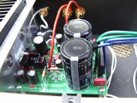
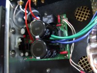
Many builders of the "Ultimate BOM," including me, used large input caps off the board. As much as I can remember, no one took extraordinary precautions about twisting the pair of leads, and all the amps ran quietly. This is too much excitement about what is most likely an unimportant issue. It's best to put at least one lead of the cap directly into its pad on the PCB, with the other end soldered to the input lead (or even the RCA jack itself, if it will reach), and keep the cap as close as possible to the board. Two inches may be too far away. The negative pole input lead can go directly to its proper place on the pcb. Chances are very good there will not be significant interference or noise. If there is, then you will need to refine your wiring. Until then, don't worry about it.
In fact, I would say it's more important to secure the input cap against a solid surface to reduce vibration as much as possible than it is to obsess over an inch or two of untwisted lead wire.
Here are bad pics of very good amps that ran perfectly silent with off-board caps and untwisted input leads.
Peace,
Tom E
Attachments
- Home
- Amplifiers
- Chip Amps
- The new "My Ref" Rev C thread