


The new Red Baron DAC Module V5.0
Posted 19th June 2013 at 10:30 AM by dvb projekt
Updated 12th January 2017 at 10:21 AM by dvb projekt (Stock status updated)
Updated 12th January 2017 at 10:21 AM by dvb projekt (Stock status updated)
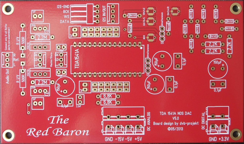
The new Red Baron
V5.0
V5.0
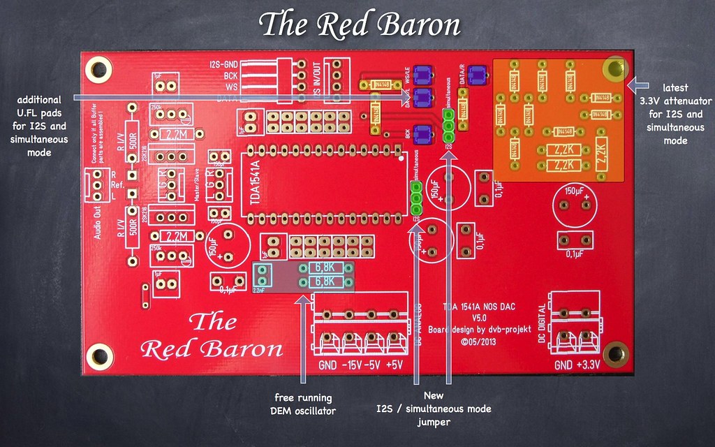
The evolution brings the following changes
- Jumper for I2S / simultaneous mode
- latest 3.3V attenuator for I2S & simultaneous mode (by -ecdesigns-)
- free running DEM oscillator (by -ecdesigns-)
- additional U.FL pads for I2S & simultaneous mode
- Separate U.FL-GND route to Digital-GND
Still on the module
- Separate I2S-GND route to Digital-GND
- Separate Analog Output GND route
- Separate GND route for active divider decoupling caps to Analog-GND
- Modified active divider decoupling pads for better SMD 1210 caps soldering
- Un-interrupted ground plane
- Direct shunt voltage inputs with shortest onboard traces
- I2S In-/Outputs with shortest onboard traces
- Onboard Grounded-Gate MOSFET Current Buffer I/V Stage
(-ecdesigns- MK7 version)
- Separate GND-Trace for I2S / simultaneous mode attenuator
- Master/Slave connectors for parallel DAC module usage and external I/V Buffer stages e.g. Tube-I-zator & DDNF Stage
- no SMD Design
The PCB has the following data:
Material: FR4 - 2mm
Layers: 2
Board size: 125x73 mm
Surface finish: Immersion Gold
Copper weight: 35µm
Soldermask: Both sides - red
Silkscreen: Legend on top
Sold out
The price will be as followed:
Professional 2-Layer PCB: $15
Worldwide shipping: $ 9
Europe shipping: $ 5
paypal fee: 3,9%
Shipping insurance on buyers request!
A donation of $3 USD to diyAudio will be done for every pcb sold.
The DAC module V2.3 will still be available for those,
who want to use it without the TDA1541A Shunt module!
If you want to use the onboard Grounded-Gate MOSFET Current Buffer I/V Stage,
you need additionally the DC-Reference Module
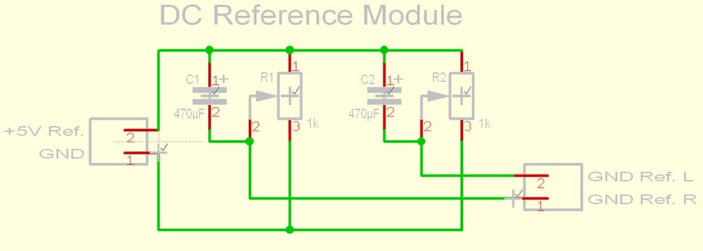
Description
Because the Grounded-Gate Buffer is connected between the DAC output and the passive I/V resistor,
normally the I/V resistor is connected between the DAC output and GND,
you must get rid off the approx. 4V DC on each I/V resistor.
Therefore we must get a new reference GND for each channel.
The circuit is connected to the ref.+5V at the output of the buffer and GND,
with a decoupling cap for each channel.
By trimming each voltage so it exactly matches DC voltage on the I/V resistor,
the DC voltage between I/V resistor and reference becomes zero.
In other words, the DC component is removed without using a coupling cap.
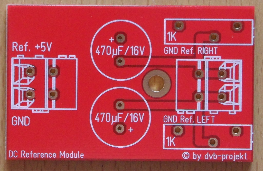
Material: FR4 - 2mm
Layers: 2
Board size: 54x34 mm
Surface finish: Immersion Gold
Copper weight: 35µm
Soldermask: Both sides - red
Silkscreen: Legend on top
Following parts are needed:
2* 2-Way vertical header; 5mm pitch - Mouser Part No.: 571-2828362
2* 470µF/min. 10V decoupling cap - Mouser Part No.: 647-RR71A471MDN1
2* 1K0 multiturn trimmer - Mouser Part No.: 652-3006P-1-102-LF
7pcs. left In Stock
The price for it is $9
Worldwide shipping: $ 4
paypal fee: 3,9%
Shipping insurance on buyers request!


