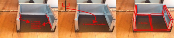
Two L-profiles inside main chassis
Hello !
* first I thought about installing a U-shaped profile in 6mm aluminium.
** probably impossible to get the correct width of a U-profile for my chassis.
*** therefore using two L-shaped alu. profiles would probably do the job very well in transfering heat. I find this solution better than installing heatsinks inside or outside of the main chassis.
**** these L-shaped alu. profiles will make contact with all surfaces next to itself.
See attached picture of what I´m thinking.
Attachments
Hi Peter,
I connected the rectifier directly to one amp board; turned the power on; bit of a flash from near the chip, then the DMM spits out -0.045 V; then when input shunted to ground 0.01V!!!! Wired up the second board the same way -0.165V to -0.015V -That offset seems too high?
Cheers,
Tim
I connected the rectifier directly to one amp board; turned the power on; bit of a flash from near the chip, then the DMM spits out -0.045 V; then when input shunted to ground 0.01V!!!! Wired up the second board the same way -0.165V to -0.015V -That offset seems too high?
Cheers,
Tim
So you got 45 and 10mV on first board, which is perfectly fine. The other shows 165 and 15mV, which although excessive for former still possible with some chips and if your source has low output impedance you'll be seeing reading close to 15mV anyway when source is connected.
Thanks Peter,
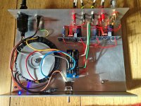
I have modified my chassis and connected the boards directly to the 3 mm thick aluminium base which will hopefully be an adequate heat-sink. I have also change the position of the rectifier board to the opposite side of the dividing wall (I will send pictures later today).
During testing last night I dropped a metal M3 nut (used in building the chassis) onto the input pads of the rectifier board whilst it was powered. It shorted the AC input and blew the fuse. There is no output from the rectifier board....the saga continues....
Cheers,
Tim
Hi Peter,
I purchased new diodes which arrived today. I installed them on the second rectifier board and attached the transformer secondary winding wires to it. All tested ok ~28 VDC between +-V & +-PG respectively. Then I connected the rectifier to the amp boards and measured the output of the rectifier again but this time it's ~70 VDC. There is also no out put from either speaker wires i.e. 0 VDC.
I haven't investigated any further i.e. removed the amp boards from the chassis. Really loosing heart with this project, terrible start to DIYAudio!!! To top it all off, I went to play some music on my existing system and found my stylus bent 90 degrees to where it should be...
Last edited:
What's wrong with my wiring?
Hi Peter,
Thanks for the offer of sorting out my boards however I do not believe that is the problem. The boards are so simple a monkey could do it (really hope I haven't made a mistake in this instance) and I don't believe the problem to be with them.
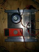
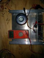
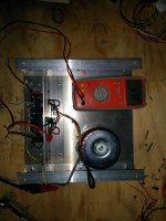
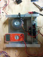
I did some further investigation and my initial findings are interesting. I measured the voltage between +- V & PG respectively and got the same results(~68V). I then repeated the measurements this time with my star ground disconnected and got normal readings (~28V). I have attached photos of my current arrangement which shows the readings for both boards, before and after disconnecting the star ground. I also measured the output voltage with the star ground disconnected and got 0.02V regardless of input shunted to ground or not. Any ideas? What is wrong with my wiring to cause this voltage disparity???
Cheers,
Tim
Hi Peter,
Thanks for the offer of sorting out my boards however I do not believe that is the problem. The boards are so simple a monkey could do it (really hope I haven't made a mistake in this instance) and I don't believe the problem to be with them.
I did some further investigation and my initial findings are interesting. I measured the voltage between +- V & PG respectively and got the same results(~68V). I then repeated the measurements this time with my star ground disconnected and got normal readings (~28V). I have attached photos of my current arrangement which shows the readings for both boards, before and after disconnecting the star ground. I also measured the output voltage with the star ground disconnected and got 0.02V regardless of input shunted to ground or not. Any ideas? What is wrong with my wiring to cause this voltage disparity???
Cheers,
Tim
Attachments
It's hard to see exact wiring from the pictures.
However, with those boards you don't need any star grounding, especially when you are testing a single channel. Check this picture: http://www.diyaudio.com/forums/atta...-gainclone-kit-building-instructions-jump.jpg
There are four jumpers between amp board and rectifier board. Duplicate those jumpers in your setup and remove any other wires.
All you need then is two wires for input signal and two wires for output. I assume transformer is dual secondary and four wires from transformer are correctly connected to AC1 and AC2.
Now, if the amp channel works fine with proper offsets and so, connect the other channel by adding jumper connections to the other board(again, forget about any star grounding, it's not needed at this point).
If you won't be getting any hum in your speakers you can leave it at that and it will work perfectly fine.
However, with some source equipment the ground loops may form and you will need star ground for power. It's been explained in this link: http://www.diyaudio.com/forums/audi...-kit-building-instructions-4.html#post1518369
What you need to do is run a wire between OG (output ground) pads and connect PG+ and PG- wires from rectifier board directly to central point on that wire. That will create power star ground and eliminate any hums you might be getting.
And that's about all.
...There are four jumpers between amp board and rectifier board. Duplicate those jumpers in your setup and remove any other wires.
All you need then is two wires for input signal and two wires for output. I assume transformer is dual secondary and four wires from transformer are correctly connected to AC1 and AC2.
Now, if the amp channel works fine with proper offsets and so, connect the other channel by adding jumper connections to the other board(again, forget about any star grounding, it's not needed at this point).
If you won't be getting any hum in your speakers you can leave it at that and it will work perfectly fine.
Thanks very much Peter.
To clarify I have sketched up the rectifier and amp boards (and excluded all points that are not used) showing the wiring as I have interpreted it from your explanation above. Could you please confirm the wiring diagram is correct? If it is, how is an earth connection achieve for the three boards as they are not drawn with an earth connection and my transformer does not have one either?
Cheers,
Tim
Attachments
Last edited:
Thanks very much Peter.
To clarify I have sketched up the rectifier and amp boards (and excluded all points that are not used) showing the wiring as I have interpreted it from your explanation above. Could you please confirm the wiring diagram is correct? If it is, how is an earth connection achieve for the three boards as they are not drawn with an earth connection and my transformer does not have one either?
Your transformer is not center tapped, so there is no earth connection between transformer and three other boards.
The grounds are separate for positive and negative supply rails and they all connect at some convenient point. They normally connect on amp board and your drawing is correct.
However, in some cases ground loops can form and cause humming. So my preferred grounding arrangement is star ground at the output.
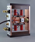
I'm posting here an image I just received from another person who finished the amp recently. That picture shows very nicely all the wiring, especially the star grounding and in this case, the common point for all the grounds is jumper between negative binding posts.
The chassis is grounded through power entry module Earth tab. I don't see output ground connected to this point, but normally I run another wire from common audio ground point to a chassis point through 10R resistor.
Attachments
Last edited:
Hi Peter,
Thanks for that. I have had a partial success today. I measured the offset after connecting the grounds as per my drawing: Right Channel -0.017 to - 0.061 (44 mV); Left channel 0.03 to -0.012 (15 mV). I haven't investigated any further as to why the left channel is so low, but will do during the week. Any ideas or suggestions as to where to look will be appreciated!
I connected my (other) turntable (as my primary stil has the busted needle) via my Project pre-amp and my speakers. Really happy to get some sound out of it. Sounded pretty good, I'm no audio buff or have much experience with quality stereo equipment so can't really describe the sound using the 'proper' adjectives apart from it was bloody loud, clear, didn't clip and was really only through one speaker! Can't wait to get both working, even if it means replacing the left channel chip (if needed or whatever it requires).
Thanks Peter.
Cheers,
Tim
You don't have to worry if it's low; the lower, the better.
Those readings are fine and the actual offsets will depend on chip itself and the combined input impedance: source and potentiometer (if present) in parallel with 22k input shunt resistor, as shown here: http://www.diyaudio.com/forums/audi...-kit-building-instructions-5.html#post1524877
Those readings are fine and the actual offsets will depend on chip itself and the combined input impedance: source and potentiometer (if present) in parallel with 22k input shunt resistor, as shown here: http://www.diyaudio.com/forums/audi...-kit-building-instructions-5.html#post1524877
Hi,
I've also just completed the premium kit, pretty nice!
However, after a few hours of use I noticed that every 10-20 minutes I get a popping sound. At first I thought since it is in both channels and also happens when my preamp is off it must be the powersupply, so I redid that and the ground wiring. The problem however persists. I noticed on one occasion, it happened first in the left channel and soon thereafter (less than a second) the right channel followed with a pop. You can also hear a soft tick when you turn the lights on in the same room, but this isn't as loud a popping sound.
I might mention, that at first startup the amplifier was extremely sensitive to proximity of my phone, cracks and pops and everything. Not the usual sound I was expecting from phone proximity. That went away after a while.
I'm going to try and add a noise filter cap to the power line in front of the amp and see if it makes a difference.
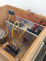
Do you have any suggestios as to what else might cause this pop? A faulty chip or maybe something with the Panasonics? This one is built into a wine crate.
Best,
I've also just completed the premium kit, pretty nice!
However, after a few hours of use I noticed that every 10-20 minutes I get a popping sound. At first I thought since it is in both channels and also happens when my preamp is off it must be the powersupply, so I redid that and the ground wiring. The problem however persists. I noticed on one occasion, it happened first in the left channel and soon thereafter (less than a second) the right channel followed with a pop. You can also hear a soft tick when you turn the lights on in the same room, but this isn't as loud a popping sound.
I might mention, that at first startup the amplifier was extremely sensitive to proximity of my phone, cracks and pops and everything. Not the usual sound I was expecting from phone proximity. That went away after a while.
I'm going to try and add a noise filter cap to the power line in front of the amp and see if it makes a difference.
Do you have any suggestios as to what else might cause this pop? A faulty chip or maybe something with the Panasonics? This one is built into a wine crate.
Best,
Attachments
However, after a few hours of use I noticed that every 10-20 minutes I get a popping sound. At first I thought since it is in both channels and also happens when my preamp is off it must be the powersupply, so I redid that and the ground wiring. The problem however persists. I noticed on one occasion, it happened first in the left channel and soon thereafter (less than a second) the right channel followed with a pop. You can also hear a soft tick when you turn the lights on in the same room, but this isn't as loud a popping sound.
Try this mod: http://www.diyaudio.com/forums/audi...-kit-building-instructions-3.html#post1516522
- Home
- More Vendors...
- Audio Sector
- Commercial Gainclone kit- building instructions