Technical question: three chassis setup: umbilical chord
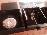
- so I'm almost finished with all mechanical parts. The only thing I now have to be certain about:
Using this umbilical chord and connectors that I have:
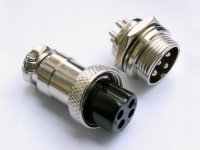
Four pin connector w. Shielding - ser attached photo.
I want to have a 5th wire ( ground ) in the umbilical chord in my setup.
1. Is it correct to connect this 5th wire to the metal frame / metal connector on each end of the umbilical wire?
2. Is it then also correct for me to connect the ground pads on the two main amplifier boards in the main chassis to each separate metal connector from each power amp ( I'm using dual power with two separate power chassis ) - and in the end connecting this circuit to chassis of main amp?
Please fill in if something's wrong. I also see that this is a topic that has been often discussed - and with different opinions stated- Remember : I want the fifth wire included in my setup between my two power modules and my main amp chassis.
PS: I have no problem understanding the grounding between the MEM / and transformer and the chassis of each power module.
- so I'm almost finished with all mechanical parts. The only thing I now have to be certain about:
Using this umbilical chord and connectors that I have:
Four pin connector w. Shielding - ser attached photo.
I want to have a 5th wire ( ground ) in the umbilical chord in my setup.
1. Is it correct to connect this 5th wire to the metal frame / metal connector on each end of the umbilical wire?
2. Is it then also correct for me to connect the ground pads on the two main amplifier boards in the main chassis to each separate metal connector from each power amp ( I'm using dual power with two separate power chassis ) - and in the end connecting this circuit to chassis of main amp?
Please fill in if something's wrong. I also see that this is a topic that has been often discussed - and with different opinions stated- Remember : I want the fifth wire included in my setup between my two power modules and my main amp chassis.
PS: I have no problem understanding the grounding between the MEM / and transformer and the chassis of each power module.
Attachments
Hi,
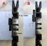
Look good, but I saw that you used 3 plates of alu, what is thickness of one ?
I hope that there is no air between each.
Phil.
... Yes, the only thing I managed to source locally at the moment.
These alu plates are screwed together with 5 screws and fasteners to the rest of the chassis. I have just dry-tested these plates- they are not fixed at the moment. No space between them, they are all straight.
They are 3mm + 2mm + 2mm = a total of 7mm thick.
I was thinking of using thermal paste between each plate.
Will my solution cause any problem?
will appreciate all inputs !
sorry.
2x25V on each transformer.
( 25V instead of 22V because I have 16ohm speakers )
spec sheet:
http://www.amplimo.nl/images/downloads/ds standardrange/78016.pdf
2x25V on each transformer.
( 25V instead of 22V because I have 16ohm speakers )
spec sheet:
http://www.amplimo.nl/images/downloads/ds standardrange/78016.pdf
Last edited:
2nd try. This is difficult for me to understand.
- so I'm almost finished with all mechanical parts. The only thing I now have to be certain about:
Using this umbilical chord and connectors that I have: A four pin umbilical setup WITHOUT SHIELDING
I want to have a 5th wire ( ground )
A FIFTH WIRE BETWEEN EACH POWER CHASSIS AND THE MAIN CHASSIS.
2. In this setup is it correct for me to connect the ground pads on the two main amplifier boards to the main chassis - attached to same place where the two 5th wire (ground ) is connected from each power amp?
Yes, that would be correct
Hi Peter, just bought your Premium Kit.
I was curious if i could replace the 1500uF 50v Panasonic FC Capacitors With 1000uF 50v Elna Silmic II's without running into problems.
Also, i wanted to use all Kiwame resistors. Will 2W or 5W Kiwame resistors fit the board in all places?
Also, i was curious on if you think there are any better diodes than the MUR860. Someone mentioned that you have tried the MSR860.
I bought the full priced premium kit instead of just the boards because i knew i would be asking you questions, and wanted to compensate you well lol. Thanks for your time!
I was curious if i could replace the 1500uF 50v Panasonic FC Capacitors With 1000uF 50v Elna Silmic II's without running into problems.
Also, i wanted to use all Kiwame resistors. Will 2W or 5W Kiwame resistors fit the board in all places?
Also, i was curious on if you think there are any better diodes than the MUR860. Someone mentioned that you have tried the MSR860.
I bought the full priced premium kit instead of just the boards because i knew i would be asking you questions, and wanted to compensate you well lol.
Thanks for your time!You are welcome to experiment, however, personally I wouldn't change anything in a Premium Kit, except for Black Gates if those would be still available or less costly.
I did some capacitors evaluation in a past and those were my conclusions:
http://www.diyaudio.com/forums/digi...gate-caps-out-production-so-2.html#post574431
http://www.diyaudio.com/forums/chip...ut-any-comments-suggestions-8.html#post581230
Elna Silmic seems like a good cap, but to me it sounded a bit cold and clinical.
The kit uses presently 680R 2W Kiwame, the other premium resistors are 22K Caddocks and they definitely sound better in their spots than Kiwame or even Vishays S102.
I was using MSR860 in a DAC, but in the amp MUR860 sounded better to me.
Too low output power ?
Hi,
I'm very pleased building these 2 LM3875 kits, but testing output power, I get low results. Have I missed something
Power rails : +/- 32.5 Vdc everywhere, dual mono wiring (2 x 0-21 Vac / 300 VA).
Dummy load : 6.8 Ohms / 100 watts well heat sinked. 100 Hz sine wave. Clipping monitored on an analogue scope.
Power output left/right modules:
27.4 w / 26 w (13.65 Vrms / 13.30 Vrms). Input voltage: 0.41 Vrms. With these values, voltage gain is correct (30).
It is far from 40 watts @ 8 Ohms, as with 6.8 Ohms, that value should be even higher (55 watts if I understand well the chart of "Output power vs supply voltage" @ post #20).
Is there a bug in my work. Could it be I checked clipping too conservatively (perfect waves) ?
Thank you in advance,
Alain
Hi,
I'm very pleased building these 2 LM3875 kits, but testing output power, I get low results. Have I missed something
Power rails : +/- 32.5 Vdc everywhere, dual mono wiring (2 x 0-21 Vac / 300 VA).
Dummy load : 6.8 Ohms / 100 watts well heat sinked. 100 Hz sine wave. Clipping monitored on an analogue scope.
Power output left/right modules:
27.4 w / 26 w (13.65 Vrms / 13.30 Vrms). Input voltage: 0.41 Vrms. With these values, voltage gain is correct (30).
It is far from 40 watts @ 8 Ohms, as with 6.8 Ohms, that value should be even higher (55 watts if I understand well the chart of "Output power vs supply voltage" @ post #20).
Is there a bug in my work. Could it be I checked clipping too conservatively (perfect waves
) ?Thank you in advance,
Alain
Hey peter, I'm putting together your kit!
I'm going to use the stock (premium) parts then play around with different components after I have a good grasp on the stock components 'sound'. I'll report my findings once completed.
I was curious on if Rf, R2, or R3 have equal impact on sound, or if there is an order from most impact to least.
Also, have you tried Z-foil resistors? I've heard many great things about them.
- Home
- More Vendors...
- Audio Sector
- Commercial Gainclone kit- building instructions