I did this by ear, I only have a multimeter and do not know how to measure noise with it other than measuring DC. Hum was absent before, interference level from a phone is alot lower in volume and I could not detect the pop during a listen session of 1.5 hour yesterday evening. This might be a bit too short to be certain, but I'm hopeful.
DC was 65~66mV in both channels before, I can measure again tonight to see if that changed anything.
Best,
DC was 65~66mV in both channels before, I can measure again tonight to see if that changed anything.
Best,
It appears DC voltage is less, with preamp set to 0. About 44mV versus 51mV left/right.
mVac without load looks pretty high to me on the right, starts high but goes down to 110~130mVac allthough I can't hear anymore noise on the right than on the left. Left channel was about 40mVac. My meter only goes down to 2Vac as scale.
Regards,
mVac without load looks pretty high to me on the right, starts high but goes down to 110~130mVac allthough I can't hear anymore noise on the right than on the left. Left channel was about 40mVac. My meter only goes down to 2Vac as scale.
Regards,
I think your DMM is not reading accurately on that 1.999Vac scale.
These 100mVac and 40mVac measurements, if correct, would indicate terrible noise at the speakers. 40mVac is ~-37dBW. i.e. a 86dB/W speaker would output 49dB @ 1m.
But that is not what you are reporting.
Get, or borrow, a meter that has a 199.9mVac scale and also reasonable tolerance on that scale.
These 100mVac and 40mVac measurements, if correct, would indicate terrible noise at the speakers. 40mVac is ~-37dBW. i.e. a 86dB/W speaker would output 49dB @ 1m.
But that is not what you are reporting.
Get, or borrow, a meter that has a 199.9mVac scale and also reasonable tolerance on that scale.
Hi Peter,
From your previous comments you have said that the offset for each chip will vary and the lower the better. So I assume the target offset is 0mV? Does it also matter if the offset differs greatly between chips, in my case I measure offset values of 0.044 V on one channel and 0.150 V on the other? Does this influence the performance of the amplifier and if so are there techniques that can improve the performance? I use the adjective 'performance' as I don't know what metric to use. I am ignorant of implications of offset and in fact what it actually means. I would appreciate any links and/or explanations which describe it, as I am sure other would be who I know are in my situation i.e. ignorant but wanting to learn.
Thank you in advance
Tim
Lm4780 repurposed power transformer
Peter,
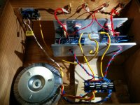
I am about to construct one of your wonderful kits and could use some advice please. I have a power transformer from an old Sugden P51 (~50 watt/ch) class AB power amplifier that I would like to use along with the chassis. The dual LM4780 kit power supplies seems to want a transformer with 2 secondary windings (|_| + |_|). The Sugden transformer has dual secondary windings with center taps (|_|_| + |_|_|). The voltage reading across the secondary winding is 60 volts AC and half that for the center tap. I was thinking of using 1 power supply circuit/board to drive 2 LM4780 circuits/boards in bridged mode, using the 2 x 60 volt secondary windings.
The Sugden power supply made use of 4 capacitors with the center tap as ground.
Can you suggest the best power supply design based on the transformer?
My thanks in advance
Peter,
I am about to construct one of your wonderful kits and could use some advice please. I have a power transformer from an old Sugden P51 (~50 watt/ch) class AB power amplifier that I would like to use along with the chassis. The dual LM4780 kit power supplies seems to want a transformer with 2 secondary windings (|_| + |_|). The Sugden transformer has dual secondary windings with center taps (|_|_| + |_|_|). The voltage reading across the secondary winding is 60 volts AC and half that for the center tap. I was thinking of using 1 power supply circuit/board to drive 2 LM4780 circuits/boards in bridged mode, using the 2 x 60 volt secondary windings.
The Sugden power supply made use of 4 capacitors with the center tap as ground.
Can you suggest the best power supply design based on the transformer?
My thanks in advance
Attachments
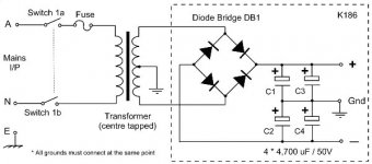
Your 60Vac centre tapped transformer is equivalent to 30-0-30Vac.
That is considered too high for all the National Chipamps that are limited to less than or equal to +-42Vdc supplies when signal is present.
The highest one can use is probably 230:28-0-28Vac used on a 220Vac mains supply, or
230:26-0-26Vac used on a 240Vac mains supply.
Your Sugden may be rated for 120/240Vac and that will help slightly. Does it have multiple primary taps?
You really need to measure and predict the worst case maximum voltage you will get from your proposed PSU, BEFORE you connect capacitors and/or chipamp.
Andrew,
Thank you for responding so quickly to my question. My house hold line voltage in Canada is 120 volt at 60 hz. The Sugden transformer has multiple primary taps; 0, 110,120, 220, 230 & 240.
Are you suggesting perhaps using the 110 volt primary to drop the secondary voltage to < 30 volts?
Ron
Thank you for responding so quickly to my question. My house hold line voltage in Canada is 120 volt at 60 hz. The Sugden transformer has multiple primary taps; 0, 110,120, 220, 230 & 240.
Are you suggesting perhaps using the 110 volt primary to drop the secondary voltage to < 30 volts?
Ron
OK Peter,
Finally success with my amp although success was probably achieved after my initial build. So since my last post I have literally stripped one board, rebuilt it with a few new components, tested it and found the re-built board was working fine but I was now getting the same problem with the other board - One channel would play music but no mid or low end and it sounded distance. So then I suspected my wiring from the rectifier to the boards, so stripped that and tried every combination, still no change, I tested every component and they all measured correctly. When I connected the boards back up to the speakers, the board I had fixed first was now not working again but the other one was. And then it dawned on me...it's my freaki' speaker that's the problem! OMG I feel like such an idiot...I changed my speakers over and it's playing fine now through both channels. I have wasted probably close to 100 hours or so over the last 5 weeks and $100 buying new components/wiring chasing a problem that didn't exist! At least I learnt a lot from it.
Now just need to build a new chassis for it all!
Cheers,
Tim
Hi,
I have not yet finished my Audiosector kit.
I´m sorry for not posting sooner, but my project has been at a standstill since I last posted.
UPDATES:
I.
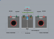
I have now three different larger chassis. 230X230 mm ( height = 80mm )
Two; for each power supply.
One for the amplifier.
They all have the same dimensions
See attached jpeg file named LAST DIGITAL SKETCH.
II.
I have now also a shaft extension kit for my DACT stereo attenuator that I will install in this amp.
THIS MEANS:
That I have all parts needed for this build.
FURTHER QUESTIONS:
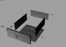
My new chassis has the following thickness dimensions :
two sidepanels ( heatsinks ) = 10mm.
frontplate =10mm.
backplate = 3mm.
and
top and bottom panel = 1mm.
See attached jpeg file named THICKNESS OF CHASSIS
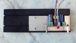
Will the main chassis; where the amp boards will be installed ; work well in transferring heat from the LM3875 chipset?
PS: I will keep you posted on this further build to be certain I get this right first time around ;-)
I have not yet finished my Audiosector kit.
I´m sorry for not posting sooner, but my project has been at a standstill since I last posted.
UPDATES:
I.
I have now three different larger chassis. 230X230 mm ( height = 80mm )
Two; for each power supply.
One for the amplifier.
They all have the same dimensions
See attached jpeg file named LAST DIGITAL SKETCH.
II.
I have now also a shaft extension kit for my DACT stereo attenuator that I will install in this amp.
THIS MEANS:
That I have all parts needed for this build.
FURTHER QUESTIONS:
My new chassis has the following thickness dimensions :
two sidepanels ( heatsinks ) = 10mm.
frontplate =10mm.
backplate = 3mm.
and
top and bottom panel = 1mm.
See attached jpeg file named THICKNESS OF CHASSIS
Will the main chassis; where the amp boards will be installed ; work well in transferring heat from the LM3875 chipset?
PS: I will keep you posted on this further build to be certain I get this right first time around ;-)
Attachments
the front panel will be able to spread the heat out better than any of the thin panels.
I had the same problem with the same hifi2000 case and LM3875..
I add a plate of alu (4mm)..
Phil.
Attachments
- Home
- More Vendors...
- Audio Sector
- Commercial Gainclone kit- building instructions