Kimber PBJ has been around for over 20 years and it's probably best known Kimber product.
Two wires for ground certainly improve shielding. There are other versions of this cable with single silver conductor for signal and two copper conductors for ground, and then there is a balanced versions where each wire is connected separately.
Two wires for ground certainly improve shielding. There are other versions of this cable with single silver conductor for signal and two copper conductors for ground, and then there is a balanced versions where each wire is connected separately.
Attachments
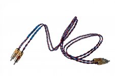
Low resistance in a return wire that shares it's duty with another circuit is an advantage.But why would Kimber do this? What is the point in having two wires for the return and only one wire for the signal? Has it got anything to do with shielding and the way they braid the wires?
Regards, Frederick Joan
The better way is to ensure the return wire does NOT SHARE it's duty with another circuit. I just googled kimber pbj to find it is a plaited 3wire cable, as is most of their cables/interconnects.
Twisted pair is better, less inductance and less interference.
star quad is better again, less interference at the expense of more capacitance.
Last edited:
Hi,
I agree that Andrew said..
And a good way is when return wire is 1,5 to 2 bigger..
For example ( diy interconnect cable I build) :
for hot : awg 29 and awg 24
for return (cold) : awg 26 and awg 22
Two wires in same ptfe tubbing, and both twisted, or better with 4 tubbing in quad setup. But it's not easy to twisted 4 ptfe tubbing !
Generaly I use only solid copper (not several strands), but you can use silver for one or more wires, depends of taste.
Cables are unshielded for small lenght, max 0,8 meter.
Phil.
Low resistance in a return wire that shares it's duty with another circuit is an advantage.
I agree that Andrew said..
And a good way is when return wire is 1,5 to 2 bigger..
For example ( diy interconnect cable I build) :
for hot : awg 29 and awg 24
for return (cold) : awg 26 and awg 22
Two wires in same ptfe tubbing, and both twisted, or better with 4 tubbing in quad setup. But it's not easy to twisted 4 ptfe tubbing !
Generaly I use only solid copper (not several strands), but you can use silver for one or more wires, depends of taste.
Cables are unshielded for small lenght, max 0,8 meter.
Phil.
Hi,
I agree that Andrew said..
And a good way is when return wire is 1,5 to 2 bigger..
For example ( diy interconnect cable I build) :
for hot : awg 29 and awg 24
for return (cold) : awg 26 and awg 22
Two wires in same ptfe tubbing, and both twisted, or better with 4 tubbing in quad setup. But it's not easy to twisted 4 ptfe tubbing !
Generaly I use only solid copper (not several strands), but you can use silver for one or more wires, depends of taste.
Cables are unshielded for small lenght, max 0,8 meter.
Phil.
Hello Phil, do you have a picture of your diy quad cable? I would like to see how you braid it. What solid copper wire do you use and why solid core? Is it silver plated? Can you recommend good value brands?
How would you describe the sound of silver as compared to copper in this setup? I have been using a shielded, 0,5m Silver interconnect from Siltech for many years in my system with good results but I also know that some can sound too bright/forward or clinical if you want. And I expect that I would be inclined to prefer the more warmer full bodied sound with the Gainclone.
Regards, Frederick Joan
WHEN the ReturnHi,
I agree that Andrew said..
And a good way is when return wire is 1,5 to 2 bigger..
For example ( diy interconnect cable I build) :
for hot : awg 29 and awg 24
for return (cold) : awg 26 and awg 22
Two wires in same ptfe tubbing, and both twisted, or better with 4 tubbing in quad setup. But it's not easy to twisted 4 ptfe tubbing !
Generaly I use only solid copper (not several strands), but you can use silver for one or more wires, depends of taste.
Cables are unshielded for small lenght, max 0,8 meter.
Phil.
SHARES it's duty with another circuit.
When the interconnect Return is dedicated to ONE CIRCUIT, there is NO advantage to using a lower resistance return wire !!!!!!!
Don't use plaited wires for interconnects.Hello Phil, do you have a picture of your diy quad cable? I would like to see how you braid it. What solid copper wire do you use and why solid core? Is it silver plated? Can you recommend good value brands?
How would you describe the sound of silver as compared to copper in this setup? I have been using a shielded, 0,5m Silver interconnect from Siltech for many years in my system with good results but I also know that some can sound too bright/forward or clinical if you want. And I expect that I would be inclined to prefer the more warmer full bodied sound with the Gainclone.
Regards, Frederick Joan
Don't use corroded silver wires for interconnects. This also includes corroded silver plating of copper cored wires.
At very high frequencies there is some small advantage to using a pure copper coating, or a pure silver coating, on wires to minimise the increase in apparent resistance due to "skin effect". BUT !!!! at these very high frequencies resistance is usually not that important, impedance is becoming the dominant criteria.
Silver coating on VHF signal wires will reduce resistance, it will not significantly reduce impedance.
Corroded silver coating on wires is of absolutely no benefit whatsoever.
Last edited:
Hi Joan,
I think the best way to twisted 4 wires is :
My old phone from about 1930, today nothing new about twisting..
With ptfe tubbing it's not easy to make same, with cotton or silk it's possible.
So with thick tube :
Observe a CAT5 or 6.. how it's twisted.
Don't use platted wire, no so good for mid and hight due by MDI (microwave discharge interface, I don't knaw if right name in english), sound is "uptight".
Quality of ofc wire is not very important, at this time all are very close..
Metals have a sound, look at Isoda cable with three metal.
Basically, copper is better for bass and mid bass, alu is better for mid, silver is better for mid and hight. tin and lead are bad for all !
So, always compromize..
The best cable does not exsiste..
Phil.
I think the best way to twisted 4 wires is :
An externally hosted image should be here but it was not working when we last tested it.
My old phone from about 1930, today nothing new about twisting..
With ptfe tubbing it's not easy to make same, with cotton or silk it's possible.
So with thick tube :
An externally hosted image should be here but it was not working when we last tested it.
Observe a CAT5 or 6.. how it's twisted.
Don't use platted wire, no so good for mid and hight due by MDI (microwave discharge interface, I don't knaw if right name in english), sound is "uptight".
Quality of ofc wire is not very important, at this time all are very close..
Metals have a sound, look at Isoda cable with three metal.
Basically, copper is better for bass and mid bass, alu is better for mid, silver is better for mid and hight. tin and lead are bad for all !
So, always compromize..
The best cable does not exsiste..
Phil.
Hi Peter,
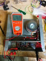
I have connected my transformer to the rectifier board (the amps are not connected yet) and noticed a hum from the transformer when it's powered up. The hum isn't very loud but can be easily heard in a quiet room up close. What is the cause of the hum and what can I do about it?
I also measure the voltage between the V+ and PG+ (as well as the the negative side) and measured +-9.45 V. In your instructions you specify +-20 Volts. My transformer is a 250 VA 25 + 25 on 230 VAC. Any advice and assistances is greatly appreciated!
Cheers,
Tim
should give ~26Vac to 27Vac on each secondary winding. Check this.My transformer is a 250 VA 25 + 25 on 230 VAC
At the smoothing capacitors after the bridge rectifier you should have ~ 36Vdc to 40Vdc. Check this.
Post a sch of your PSU.
There are at least two ways to use your dual secondary transformer.
These are wired differently.
I have connected my transformer to the rectifier board (the amps are not connected yet) and noticed a hum from the transformer when it's powered up. The hum isn't very loud but can be easily heard in a quiet room up close. What is the cause of the hum and what can I do about it?
I also measure the voltage between the V+ and PG+ (as well as the the negative side) and measured +-9.45 V. In your instructions you specify +-20 Volts. My transformer is a 250 VA 25 + 25 on 230 VAC. Any advice and assistances is greatly appreciated!
There's no capacitors on rectifier board, so the measured voltage should be expected low. After checking that voltage polarity is OK, you can hook it up to amp board, where the smoothing caps are located, and then measure the voltage. You will see that it's much higher after smoothing.
As to transformer noise, some people complain about it, and in most cases it is due to DC present on the mains:
http://www.diyaudio.com/forums/power-supplies/245129-blocking-mains-dc-offset.html
Hi Peter,
Thanks for your prompt reply.
AndrewT thanks for yours also.
I have rectified the "alleged" problem of the low voltage - operator error! After measuring it properly I am getting around 28.7 Volts on both boards, measured at the connection to the amp board.
The hum persists and I'll have to wait until I connect the amp up to determine whether it's going to be a problem or not.
My next problem is the measurement of the DC Output Voltage - I measure -9.61V at both speaker terminals, regardless of the position of the volume pot. Any ideas as to why?
Cheers,
Tim
Attachments
My next problem is the measurement of the DC Output Voltage - I measure -9.61V at both speaker terminals, regardless of the position of the volume pot. Any ideas as to why?
I have a feeling that it's also "operator's error"
Hi Peter,
Thanks for the prompt reply. Any suggestions as to what the operator might be doing wrong? I was a bit more diligent in my testing this time round and checked I hadn't made the same mistake again. I have checked my wiring and as far as I can tell it appears to be correct...or maybe not!
Cheers,
Tim
Thanks for the prompt reply. Any suggestions as to what the operator might be doing wrong? I was a bit more diligent in my testing this time round and checked I hadn't made the same mistake again. I have checked my wiring and as far as I can tell it appears to be correct...or maybe not!
Cheers,
Tim
What wires to use in MEM
Hello!
I have one quick question:
I have the following wires from Cardas :
17.5 AWG in both black, red and blue colours
19 AWG in both black, white
All stranded wires.
Should I use the 17.5 AWG wire between the different parts of the MEM?
PS : I will solder the wires to the terminals on the MEM, will also use shrinking tubes to isolate each terminal.
PS2 : I will use a standard wire from an electrical cable ( green / yellow ) for the wire going from the ground input in the MEM to the ground connector fastened to chassis.
- Home
- More Vendors...
- Audio Sector
- Commercial Gainclone kit- building instructions