cc. email, posted here since others probably have the same problem:
See page 9 of the catalog.
For 115V nominal:
Primary
AC live: black, violet
AC neutral: yellow, red
Secondary
to ~ of first rectifier: green, red
to ~ of second rectifier: brown, blue
The voltages wont measure correctly until you actually connect to the VSPS. When you do, you can expect V++ to be about 17 V and V-- to be about -17 V.
Rest of the connections as per the guide.
...
I will go through the components on that board tomorrow to make sure nothing died from the first time I played and both channels played.
...
I checked all the components visually to make sure nothing was installed incorrectly and double checked against the working board. Everything *looks* correctly installed.
The only difference between the boards was that I ran out of prp 68k 1/4w resistors for R19/20 and used takman carbon film 68k 1/4w instead. You can tell because the takmans are pink with regular resistor color codes. I will replace them when I get to order more prp's.
The board that doesn't work is the one closest to the connectors in the photo (the one with the takman's).
It is getting input power.
Are there any key test points where I could check in the pcb to isolate the problem?
Thanks again.
From the photo I can see everything looks quite neat and tidy, with no obvious problems.
Try the obvious: switch the phono cable R and L channel, to confirm the problem is not upstream.
Then confirm that power has reached the op amp socket (pin 1 and pin 7). About 10V typically.
Then replace or switch the op amp.
If the op amp is working and powered, the problem must be a signal connection inside the VSPS box or a bad solder joint on the board, or, unlikely but possible, an open circuit component in the signal path. C3 for example got smoked with you soldered it in place.
Using the multimeter, test for continuity all along the path from the input RCA to the op amp socket, and along the output path on both sides of the capacitor.
Try the obvious: switch the phono cable R and L channel, to confirm the problem is not upstream.
Connected the vsps to the amp directly and it's the vsps.
Then confirm that power has reached the op amp socket (pin 1 and pin 7). About 10V typically.
Then replace or switch the op amp.
If the op amp is working and powered, the problem must be a signal connection inside the VSPS box or a bad solder joint on the board, or, unlikely but possible, an open circuit component in the signal path. C3 for example got smoked with you soldered it in place.
Using the multimeter, test for continuity all along the path from the input RCA to the op amp socket, and along the output path on both sides of the capacitor.
Before I even attempted to check the opamp I checked the resistors to make sure they were all ok. On the bad board, I can't get resistance from R1, even if I put the multimeter leads on the resistor legs. The good board I get 46.8k. Thinking the resistor was bad I took it out, measured it and it measures ok!
I put it back in and can't get a reading, meter just shows 0.000 either on the upper, lower parts of the hole or on the legs of the resistor. R2, R3 and R7 around it measure correctly... R1 on the good board measures ok.
I checked the opamp between legs 1 (trim offset) and 7 (vc+) and I get 0.5vdc on both opamps. I think I misunderstood what you wanted me to measure...
Thanks again.
Connected the vsps to the amp directly and it's the vsps.
I was referring to the connection from the turntable to the VSPS, not the VSPS to the amp.
Before I even attempted to check the opamp I checked the resistors to make sure they were all ok.
I hope the VSPS was unplugged and fully powered down when you were doing those measurements. Otherwise it's all null and void.
I checked the opamp between legs 1 (trim offset) and 7 (vc+) and I get 0.5vdc on both opamps.
Sorry, pin 4 and pin 7. pin 4 is V- pin 7 is V+. Remove the op amp from the socket and power up the VSPS to make the voltage measurements. Black test lead to COM/ground.
I was referring to the connection from the turntable to the VSPS, not the VSPS to the amp.
Sorry, I did those too but forgot to mention it. The turntable plays fine (both channels) through my preamp using the preamp's phono stage.
I hope the VSPS was unplugged and fully powered down when you were doing those measurements. Otherwise it's all null and void.
Yes it was.
Sorry, pin 4 and pin 7. pin 4 is V- pin 7 is V+. Remove the op amp from the socket and power up the VSPS to make the voltage measurements. Black test lead to COM/ground.
Will do tonight when I get home.
Any idea why R1 would not give me a valid resistance when installed?
I've just come to realize that anyone who sells pcb's/kits and gives this kind of support over the forum/email must do it because they love it. Because by now, if you pay yourself by the consulting hour, this would've have wiped out any profits from the sale of the pcb/parts... Your help it very much appreciated. Thanks again.
Pin 7 (+vcc) & pin 4 (-vcc) with op amp removed using xlr connector's common:ISorry, pin 4 and pin 7. pin 4 is V- pin 7 is V+. Remove the op amp from the socket and power up the VSPS to make the voltage measurements. Black test lead to COM/ground.
Good board:
pin 7: -7.54v
pin 4: 15.83v
Bad board:
pin 7: 15.84v
pin 4: -7.97v
Seems like you have voltages the wrong way around. Could it be that your Q1 and Q2 are swapped or reversed?
No, but could it be that I wired the input RCAs in reverse? Thanks for the suggestion woodturner-fran, I went back to look at Q1/2 at your suggestion and noticed that the input rca's had their +/- reversed... Apparently yellow and black wires do not offer enough color contrast for my brain to process into +/- . The outputs were wired correctly. Sorry to waste so many nice people's time.
The op amps now have the right polarity, but the voltages are still 15.8v for one and 7.6/9v for the other pin. Does this qualify as "around 10v" or do I still have something wrong?
I only listened to one song, but it sounds very good (in stereo no less...).
Thanks again for your help.
I'm glad you found the problem with the RCA input wiring, but you are not out of the woods yet.
With respect to COM, the V+ and V- measured at the op amp pins should be about 10 V, let's say 8-10 V, while the V++ and V--, measured for example at the point where the power supply connects to the board, should be about 16-17 V.
As Fran suggested, you have a problem with the transistors Q1 and Q2: they are either reversed (BD135 for BD136 position), reversed (rotated 180 deg so BCE instead of ECB), or blown.
I think there is a typo in what you wrote earlier and you probably have
Good board:
pin 7: 15.83v
pin 4: -7.54v
Bad board:
pin 7: 15.84v
pin 4: -7.97v
This means the positive rail (V++) is not being regulated by the X-reg but passed as-is to the op amp. The negative rail appears to be fine. So the most likely thing is you have Q1 reversed. (pin 1 into the base instead of the emitter, BCE instead of ECB)
Last edited:
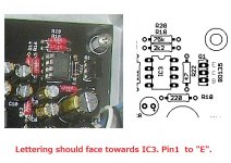
From what I can tell from the photo you posted earlier, you have Q1 oriented backwards on both boards. the heavier, longer line of the part online on the board indicated the back side of the transistor, the shorter tapered side indicates the front. The front of the transistor can be identified easily as it's the side with the lettering on it.
Attachments
Last edited:
Hi RJM,
Im going to buy the VSPS300 boards this weekend but I do have one question before i pull the trigger. I have this case and will be using it for the project. My question is, how important is it to build the power supply stage apart from the rest of the boards? Will I be wasting my time in using this case? Here is the link to the transformer I will be using. As you can see the internal depth of the case is 320mm and the 2 VSPS300 boards next to each other will be ~200mm. The OD of the transformer is 87mm. So thats about 33mm between the edge of the transformer to the vsps board. What do you think ?
Im going to buy the VSPS300 boards this weekend but I do have one question before i pull the trigger. I have this case and will be using it for the project. My question is, how important is it to build the power supply stage apart from the rest of the boards? Will I be wasting my time in using this case? Here is the link to the transformer I will be using. As you can see the internal depth of the case is 320mm and the 2 VSPS300 boards next to each other will be ~200mm. The OD of the transformer is 87mm. So thats about 33mm between the edge of the transformer to the vsps board. What do you think ?
The case and transformer you picked look good. When putting the transformer in the same case with the boards you just have to be a little careful about a couple of things.
1) The VSPS chassis in now earthed, which can in rare cases cause complications with ground loops.
2) The VSPS300 circuit is not especially susceptible to magnetic fields, and a toroid is anyway fairly "quiet", but the magnets in some unshielded MM/MI cartridges (hey Grado, I'm staring in your direction) can be adversely affected by a power transformer sitting close by. With a separate power supply it7s easier to move the transformer well away from the TT to avoid this.
Not really a caution, but it's worth noting that a separate power supply can be "reused" for different projects: you can unplug the VSPS and plug in a Phonoclone3, headphone amp, or small gainclone (for computer speakers or something).
Those are the reasons I recommend a separate power supply. 99% of the time a one-box built will work out fine.
Last edited:
Thanks Richard, it wasn't the orientation, it was that I installed the two bd135's together on one board and the two bd136's on the other... I forgot the measure twice, cut once rule. I had paired them when I took them out of the bag, but obviously didn't pair them well enough. I also damaged one board's base pad (the Q1) while removing the two wrongly placed parts and had to jumper Q1's base to the leg of R22 that is closest to the base to get the board working again (as per your recommendation).From what I can tell from the photo you posted earlier, you have Q1 oriented backwards on both boards. the heavier, longer line of the part online on the board indicated the back side of the transistor, the shorter tapered side indicates the front. The front of the transistor can be identified easily as it's the side with the lettering on it.
Thanks to all who helped, it is much appreciated.
I recently built a VSPS300 using the recommended BOM parts and there's a slight 60Hz hum in both channels both with a MM cart connected and with the inputs shorted to ground. I've checked and doubled checked all ground connections by resistance when off and then voltage when on. The voltage rails hold steady at approx +/- 9.25V. All parts are in the correct orientation. I'm completely clueless as to where it is coming from.
RJM,
I am building a protoboard version of the Xreg to power the OPA2134-based analog signal processor for my Linkwitz Orion+ speakers, which calls for about 300ma at +/-12V. In the schematic for Xreg you show one NE5532 dual opamp. In the Phonoclone 3 I built you called for a pair of OPA27. I have the choice of using either a pair of OPA27 or one OPA2134...any preference you would recommend?
I am building a protoboard version of the Xreg to power the OPA2134-based analog signal processor for my Linkwitz Orion+ speakers, which calls for about 300ma at +/-12V. In the schematic for Xreg you show one NE5532 dual opamp. In the Phonoclone 3 I built you called for a pair of OPA27. I have the choice of using either a pair of OPA27 or one OPA2134...any preference you would recommend?
Emoose:
9V rails tells you everything is working fine.
60 Hz hum with the inputs shorted tells you that the noise pickup is happening inside the case but independent of the input state.
Make sure the internal wiring is tidy: IN+ and IN- are twisted together and kept well separate from OUT+ and OUT-, and V++,COM and V-- are twisted together and well away from the input and output wires.
The VSPS300 should be in a metal case, COM connects to the chassis.
If the transformer shares the case there is a potential for hum pickup. Try lifting the "earth" connection in the power supply.
Kevin,
I use the OP27 in the Phonoclone 3 / VSPS300 for four reasons,
- its the same op amp used in the amp circuit: simpler stock list of parts
- the layout happened to be more convenient
- ultimately the performance should be better due to the lack of crosstalk
- the Xreg circuit is complementary to the phonoclone circuitry, same gain, so it was fitting to use the same op amp.
I don't have a recommendation for you, it's whatever you find more convenient.
I have read nearly every post on here and have the Phonoclone 3 boards, thanks RJM.
I have a few other phono stages I have built but this one looks intriguing. I am waiting on Comet Supply to send my Denon DL-301 Mk2 so I can finally build this and also test out my other MC phono stages.
Why does someone build MC stages without a MC cart? It's DIY sickness that's what it is.
Thanks should go to RJM for his time and effort in this, just answering all these questions deserves a lot of praise.
I have a few other phono stages I have built but this one looks intriguing. I am waiting on Comet Supply to send my Denon DL-301 Mk2 so I can finally build this and also test out my other MC phono stages.
Why does someone build MC stages without a MC cart?
It's DIY sickness that's what it is.Thanks should go to RJM for his time and effort in this, just answering all these questions deserves a lot of praise.
Hi Rjm,
I am enjoying the music from a phonoclone 3 I built with your help.
Essentially for easthetic reasons I am going to put the pcbs, already separated from the case trasnsformer, in a new chassis.
Can you tell or address me to a post where it is described how to minimise the noise level. At present I do not hear any noise from the listening position, but there is some noise with the ear near the speaker. To me it is not a trafo hum, but rather a very low rf noise.
Thank you
Renato
- Home
- Source & Line
- Analogue Source
- The Phonoclone and VSPS PCB Help Desk