The X-reg schematic is a generic example of the circuit. Resistance values are adjusted depending on the input voltage and the desired output voltage.
If you want to combine the X-reg and VSPS, this has been done already and is called the VSPS300. The circuit schematic, board layout, and parts list are all available here.
You can put the power supply together with the VSPS or separately. Separately is recommended for novice builders, while metal cases are recommended for both power supply and VSPS.
Last edited:
Thank you. The VSPS300 schematic is very helpful, didn't know it was included in the file.
I prefer building the VSPS from scratch on my own. I will use perf boards with a line pattern, drawing my own design and cutting the tracks where needed. I'll be sure to do a lot of testing (also to make sure the tracks I cut are really cut). Doing all this will give me a ton of experience, not to forget the satisfaction afterwards!
Still, if I were to order the PCB's for the VSPS 300 (without parts), can I pay through bank transfer?
Due to the high bank fees involved otherwise, I only accept Paypal payments.
"Doing all this will give me a ton of experience, not to forget the satisfaction afterwards!"
The satisfaction dividend depends on whether you ever get it working properly, though. Just sayin'.
"Doing all this will give me a ton of experience, not to forget the satisfaction afterwards!"
The satisfaction dividend depends on whether you ever get it working properly, though. Just sayin'.
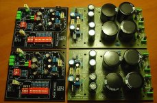
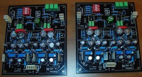
Here is my latest variation. Dual mono.
Wave files (44.1kHz - cd quallity):
MM section - Free File Hosting Made Simple - MediaFire
MC LO section - Free File Hosting Made Simple - MediaFire
K
Wave files (44.1kHz - cd quallity):
MM section - Free File Hosting Made Simple - MediaFire
MC LO section - Free File Hosting Made Simple - MediaFire
K
Attachments
Last edited:
Full dual mono.
Advanced power supply:
2 stage LM317/LM337 in series: one on pcb psu, second on pcb pre. After that finesse circuit.
MC:
- lowered R values and increased C values in RIAA section to values used in MM section. There is less gain, but sufficient.
- I stage feeds also IN+ of II stage through 2k2;
- from II stage IN+ 10uF and 232k parallel go to ground
- no cap on output
- variable gain in I stage - I like this because its useful.
MM:
- power supply like in MC section
- 12 positions dip switch for R load - dozens of possible settings from 1k to 100k
- 4 positions dip switch to set the C loading - from 0 ... 389pF
- variable gain of course ;-)
It may be used for MM and for MC HO cartridges, no matter from what producer.
Layout:
all grounds (psu and signal) comes to one point on each pre pcb.
Grounds on pcb psu are separated (for each rail) and meets together on pre pcb.
Sounds in my opinion very good ... like in wave files ;-)
Performance limits only turntable (tonearm, bearing, internal wires) and cartridge.
Cartridges used for recording:
MM - 2M Black
MC - SPU Naked
Regards Krzysztof
Ps. More pictures: https://picasaweb.google.com/115453839954675028762/NUDAPHONO#
Last edited:
Certainly DIP switches for various input configurations is a welcome addition and makes the circuit considerably more user-friendly, especially if one is of the habit to change cartridges regularly.
You are the second person today I've corresponded with who is apparently convinced that adding LM317/LM337 regulators to a circuit improves it, and adding more LM317/LM337 to the circuit improves it further.
This is simply not the case.
Voltage regulators reduce noise within their passband as 1/G but add their own broadband noise X to the output. LM317 have a passband of about 2 kHz, which means they are great for reducing 120 Hz ripple and the higher order harmonics of it, but they spew out noise over the whole audio spectrum in return.
(Attach an LM317 to a DC blocking high pass filter and connect the output to your preamp and give it a listen. Or look at the 0-100 kHz FFT. Either way it isn't pretty.)
Op amps, such as those used in the phonoclone/VSPS are great at preventing power line ripple on the power pins from getting to the output. The PSRR is well in excess of 100 dB. They are quite poor at preventing high frequency audible line noise on the power pins from getting to the output, however. By 20 kHz, the power line noise is pretty much direct coupled to the output.
Adding a second LM317 in series does not reduce ripple (any residual component after the first LM317 can easily be absorbed by the op amps to below the output noise threshold of the op amp itself) but adds another 3dB of audio band noise to the power rail.
/R
Advanced power supply:
2 stage LM317/LM337 in series: one on pcb psu, second on pcb pre.
You are the second person today I've corresponded with who is apparently convinced that adding LM317/LM337 regulators to a circuit improves it, and adding more LM317/LM337 to the circuit improves it further.
This is simply not the case.
Voltage regulators reduce noise within their passband as 1/G but add their own broadband noise X to the output. LM317 have a passband of about 2 kHz, which means they are great for reducing 120 Hz ripple and the higher order harmonics of it, but they spew out noise over the whole audio spectrum in return.
(Attach an LM317 to a DC blocking high pass filter and connect the output to your preamp and give it a listen. Or look at the 0-100 kHz FFT. Either way it isn't pretty.)
Op amps, such as those used in the phonoclone/VSPS are great at preventing power line ripple on the power pins from getting to the output. The PSRR is well in excess of 100 dB. They are quite poor at preventing high frequency audible line noise on the power pins from getting to the output, however. By 20 kHz, the power line noise is pretty much direct coupled to the output.
Adding a second LM317 in series does not reduce ripple (any residual component after the first LM317 can easily be absorbed by the op amps to below the output noise threshold of the op amp itself) but adds another 3dB of audio band noise to the power rail.
/R
Thanks RJM.
I was looking at his solution and figured since I was using your VSPS300 boards that maybe I could get other ideas on an off board solution.
I suppose Ahaja's idea could be implemented via dip switches on perf boards for each of the resistor and the cap locations. I am personaly thinking it might get a tad messy. Any thoughts on that?
The on-board load resistors and optional load capacitors can easily be replaced by a daughterboard with multiple switched options. This is "free" in that it has no negatives, just the effort to set it up.
R2 and R3 can be replaced by a single linear potentiometer to continuously adjust the gain. There are issues with channel balance, however, plus the feedback loop is expanded to include a bunch of lead wires. The difference in gain betwen 5 or 6 or 7 mV is not worth fussing over. It's less than 3 dB. Far simpler to just adjust the amplifier volume a few degrees.
R2 and R3 can be replaced by a single linear potentiometer to continuously adjust the gain. There are issues with channel balance, however, plus the feedback loop is expanded to include a bunch of lead wires. The difference in gain betwen 5 or 6 or 7 mV is not worth fussing over. It's less than 3 dB. Far simpler to just adjust the amplifier volume a few degrees.
I've designed a headphone amplifier / preamp that is a direct replacement for the VSPS300/Phonoclone 3 boards. Some of you might be interested:
http://www.diyaudio.com/forums/solid-state/183588-headphone-amplifier-drop-replacement-phonoclone-3-vsps300.html#post2476813
http://www.diyaudio.com/forums/solid-state/183588-headphone-amplifier-drop-replacement-phonoclone-3-vsps300.html#post2476813
my phonoclone:
An externally hosted image should be here but it was not working when we last tested it.
one more picture
An externally hosted image should be here but it was not working when we last tested it.
Hi Richard,
Greetings, hope everything is well in Tokyo.
Just my personal view on the phonoclone.
It has been a long time since I completed my phonoclone and very happy with the result. Currently I am having the obbligato gold as output capacitor, its very musical and lots of PRAT, overall I do feel happy as I could listen for long hours without fatique. However it is not as super sharp as compare to the mundorf oil/gold cap a friend of mine is using.
Weeks ago, I was comparing it to a FM acoustics 122, and feel that FM is superior in all parameters and has very very low noise floor and very organic sound (no mechanical noise) and vivid but my phonoclone is close to 80-85% of all the parameters and the important thing is that I am still able to enjoy the phonoclone without the urge of changing anything.
My next plan is to have the dual 225v novutem transformer to be house in seperate casing to reduce the noise floor.
The only question I would like to ask is regarding the coupling capacitor as I do feel that it really influence the character of the overall sound.
As I heard that no capacitor is the best capacitor, therefore is there a way to have a DC coupling to replace the capacitor? and how to go about it?
Thanks.
Regards.
Kyoto actually, and yes, I'm fine thanks!
Ultimately the performance of the Phonoclone 3 is limited by the op amp. If you want to build your own from transistors, as FM Acoustics apparently do, you can use low noise, parallel transistors to lower the noise, you can hand match components for low distortion, you can run the whole circuit at higher bias currents to put everything in class A, and finally you can cut out any extraneous general purpose safety stuff that most op amps have that may degrade the sound.
Is it worth it? It is worth paying the asking price of the FM acoustics 122? Your 80-85% suggest perhaps not, but in fairness a good bit of the FM acoustics price goes to cover the tremendous flexibility on offer in terms of eq. and loading options.
Certainly going to dual mono will give you some improvement, and I expect... I know... that the coupling capacitor will have a very strong influence on the sound.
What I don't know is why one capacitor sounds better than any other, especially for the same dielectric material.
The high gain of the phonoclone means the output offset voltage is quite high, perhaps as much as 1 V, so it is not really a good idea to remove the output coupling caps. You can replace it with a DC servo, with a daughter-board for the extra components.
Or you can learn to live with whatever small color creeps in as a result of the capacitor, and use one which you happen to like most.
Please, can you explane differents in PFH (peak the frequency characteristic) of my VSPS and RIAA curve?
These "humps" on 100, 1000 and 10000 Hz appears both wen powered from AS rectifier (separately unit) and from a batteries:
And here is a cirquit design:
What elements can be changed for correction ? Thank you in advance/
Sergei, Russia.
These "humps" on 100, 1000 and 10000 Hz appears both wen powered from AS rectifier (separately unit) and from a batteries:
An externally hosted image should be here but it was not working when we last tested it.
And here is a cirquit design:
An externally hosted image should be here but it was not working when we last tested it.
What elements can be changed for correction ? Thank you in advance/
Sergei, Russia.
- Home
- Source & Line
- Analogue Source
- The Phonoclone and VSPS PCB Help Desk