I posted most of this on the other Phonoclone 3 thread but it seems to be deserted.
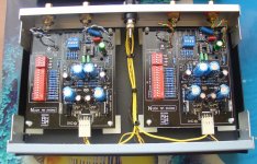
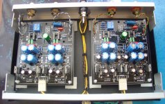
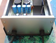
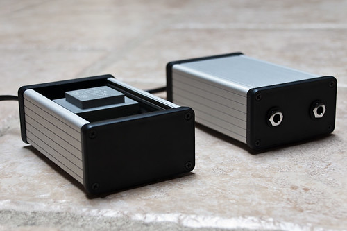
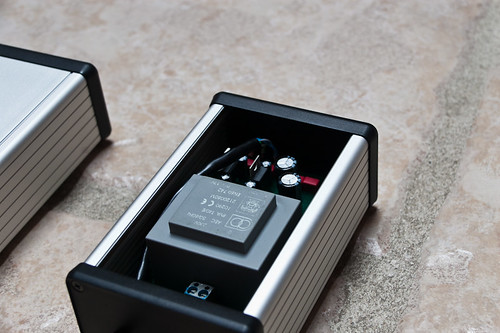
I did not use the PCB's I purchased off Richard, I etched a PCB at home and used 4 x 6v lantern batteries as a supply as I am obsessed with battery power at the moment.
I added 0.1uf ceramic caps to the 100uf filtering caps as a means of lowering noise and preventing op amp oscillation. For those trying different op amps, maybe a 33pf cap across R2 would help as well.
Mine is dead silent, I can crank the volume right up and it makes my modded CA 640P's sound noisy by comparison.
I also used 1uf Panasonic polypropylene's instead of the 2.2uf and added a 0.1uf bypass poly cap to it, it gave me a nice balance of warmth and detail. With the 2.2uf it seemed to have too much detail (shock, horror) and was a little harsh in the top end IMO.
It's the best sounding phono stage I have tried by a mile, thanks Richard for a great project.
Last edited:
Thanks!, have ordered all the parts and am looking forward to the build. Hypnotoad, yes I was following your project on the Audiokarma thread, looks good.DC resistance is listed at 12 ohms. This is the cartridge impedance.
Cartridge output is 0.5 mV.
Calc returns R1 12 Ohms (use 0-22 ohms) and R2 240 ohms (use 200-330 ohms)
Cheers,
Kirk
Thanks for sharing your build.
I'm not a big fan of battery power supplies, but if it works for you, great! Ditto ceramic bypass caps.
If batteries are noiseless power source, why does the bypass capacitor appear to lower the noise floor? Curious, no?
Richard the impedance from any power supply and ground is not zero, variations in current draw can cause tiny ripples, these ripples can cause oscillations. Adding bypass capacitors greatly reduces these ripples therefore making the opamps less prone to oscillations. Which all adds to noise. I was puzzled why these were not in the original design as others had complained about noise and some op amps not being suitable. Maybe these should be a part of the circuit, just thinking out loud here.
")
However the noise on the one I built was so low, I can crank the volume right up and hear nothing.
Interestingly enough, last evening I tried my creation using a Rod Elliot well filtered, linear PSU, the sound was all there and the noise levels low. But even my wife noticed the sound has a harshness to it, even when I did not tell her whether she was listening to batteries or the linear supply, she could pick the latter as being harsh and the batteries as being smooth. This harshness was only apparent in direct comparison to the battery supply though and the power conditioner circuit, may remove this harshness, I may build it next to see.
Is there any chance of having a PCB made with out the voltage conditioner circuit in future? It makes the circuit a lot easier to construct for us less experienced DIY'ers.
As I said this is a great project and Richard should be congratulated on making it available, I have recommended to many people to buy boards from Richard.
Last edited:
Okay I'm about to pull the trigger on the Phonoclone Kit. I'm going to hold off until I figure out how to power the darn thing. I've read 100's of pages of this thread and the dedicated Phonoclone 3 thread, and I'm still lost.
Please forgive my ignorance, but is there a beginner's kit, or step by step for building a power supply for the Phonoclone? I am really clueless when reading explainations of the right power supply to use.
Terms like " 2x12VAC sec. transformer and 1 or 2 bridge rectifiers" is absolutely Greek to me
If someone can point me in the right direction, either a book or simple kit, that would be great.
Last edited:
@Hypnotoady
Years ago when I was looking at op amp circuits I tried various bypass caps and concluded that the best-sounding configuration was to use un-byapssed, high quality electrolytics placed as close to the op amp as possible. Also, the circuit bandwidth must be limited to 200 kHz or so, and the electrolytics can cover the operating frequency range.
Putting film caps in parallel with the electrolytics resulted in a very nasty sonics.
@utahusker
I generally recommend a trip to the local library and some basic electronics textbooks. It's not hard but power supplies involve playing with line voltages so some general understanding of electricity and electronics is required, in addition to the bare information.
2x12 VAC sec : a transformer with two 12 volt secondary output windings
1 or 2 bridge rectifiers : exactly what it says.
If you don't know what a bridge rectifier is, or if the diagram below makes no sense, it's your obligation to do some self-study before starting building a Phonoclone.
Attachments
@Hypnotoady
Years ago when I was looking at op amp circuits I tried various bypass caps and concluded that the best-sounding configuration was to use un-byapssed, high quality electrolytic's placed as close to the op amp as possible. Also, the circuit bandwidth must be limited to 200 kHz or so, and the electrolytic's can cover the operating frequency range.
Putting film caps in parallel with the electrolytic's resulted in a very nasty sonics.
Interesting Richard, I was reading what op amp manufacturers recommend and across the board it is a larger power filtering cap with a smaller bypass cap for stability and low noise.
I may try on my next build, just going with the 100uf's and having a listening comparison. The noise levels I am getting at the moment are practically zero, much much quieter than my Yamaha C4 preamp which the phonoclone is connected too.
I doubt I am getting any very nasty sonics, I am not noticing any as it sounds better than any other phono stage I have tried by a mile. It has this wonderful black background that makes the voices hang in the air.

I love the clean, clear, detailed sound, without any hint of harshness. I have calculated that for $10.00 the four 6v lantern batteries cost they can power it for 750 hours before needing to replace them. And I don't have to mess with mains voltage or worry about power surges. I have them out of sight with a 3 conductor wire running to them, and one of those molex connectors.
Cheers,
Phillip
For batteries the results for different bypass caps will be different from my experience no doubt. As for batteries themselves, "clean, clear, detailed sound, without any hint of harshness" is also how I'd describe the sound, but I'd add that in addition I found (in my trials) it was overly smooth, hushed, deadened, and lacking power or pace. In a word, I'd call it "wimpy". The linear supply was lively and fast, with considerably more "oomph".
That's just my opinion, for the record, since the original discussion, which involved two or three other people doing the same test and coming to the same opinion, happened some years ago and is buried somewhere on the forum unlikely to be found by anyone.
The datasheet recommendation for bypassing holds true in general, since the bandwidth of high speed op amps can easily exceed the useful operating frequency of electrolytics. It's somewhat outdated as this is less true with modern low impedance types than it once was. But for many circuits it is still valid. The point is that I specifically have low circuit bandwidth and high-performance electrolytics, so I can - with due diligence - disregard the recommendation re. bypass caps.
For batteries the results for different bypass caps will be different from my experience no doubt. As for batteries themselves, "clean, clear, detailed sound, without any hint of harshness" is also how I'd describe the sound, but I'd add that in addition I found (in my trials) it was overly smooth, hushed, deadened, and lacking power or pace. In a word, I'd call it "wimpy". The linear supply was lively and fast, with considerably more "oomph".
That's just my opinion, for the record, since the original discussion, which involved two or three other people doing the same test and coming to the same opinion, happened some years ago and is buried somewhere on the forum unlikely to be found by anyone.
Richard,
Maybe the difference is that when using a couple of 9v batteries the capacity isn't that great. I am using batteries rated at 11 amp hour, that's twenty times that of the 9v. And with such a large surface area they don't suffer from impedance issues.
So my question is this, would it be possible to have produced a single stereo board without the Xreg circuit like I made for myself at home? For those simple minded souls like my self who can put up with battery sound, a low parts count and simplified construction? Later on they could add the Xreg circuit on a separate board/s if they desire.
I know a lot of people who would be interested in purchasing them. I know I would as I get tired of drilling all the holes in my home made PCB's.
A top shelf high or low output moving coil phono stage that can be built with almost zero noise, complete with enclosure and all hardware for less than one hundred dollars, shoot, seems too good to be true.
But as I found it isn't thanks to you Richard.
I think it would be a big seller and have people knocking down your door.
Cheers,
Phillip
Last edited:
Yes, it's quite possible that larger capacity batteries would have given me a different impression.
Just as different battery configurations sound different, so do different linear power supply configurations. With the phonoclone 3, functional with the X-reg included, all you need to power it is a transformer and diodes. That sounds much better than where the filter capacitors or regulators included the power supply itself. It's also simple to source and build.
Since you have a pair of my boards, you should give it a try sometime...
I've been reading your thread at Audiokarma.
As you've shown, when you cut the voltage regulators out the circuit layout becomes a lot simpler. The boards you made have a clean, logical layout and it's a bit of a waste to
limit them as a one off. If you want to distribute them to other DIYers, that's fine by me.
I understand that the X-reg is a bit complicated for some, and it's a lot of extra parts to source.
Finally, a note about high output MC cartridges: They might be OK, they might not. It's a bit of a toss up without knowing the coil inductance. The problem occurs if the inductive contribution to the total impedance becomes significant compared to the resistive component over the audio spectrum. Loss of high frequency intensity can result.
Your Benz is probably OK, I suspect. If you can find the coil inductance data from the instructions or someplace, I can tell you for sure one way or the other.
Yes, it's quite possible that larger capacity batteries would have given me a different impression.
Just as different battery configurations sound different, so do different linear power supply configurations. With the phonoclone 3, functional with the X-reg included, all you need to power it is a transformer and diodes. That sounds much better than where the filter capacitors or regulators included the power supply itself. It's also simple to source and build.
Since you have a pair of my boards, you should give it a try sometime...
I've been reading your thread at Audiokarma.
As you've shown, when you cut the voltage regulators out the circuit layout becomes a lot simpler. The boards you made have a clean, logical layout and it's a bit of a waste to
limit them as a one off. If you want to distribute them to other DIYers, that's fine by me.
I understand that the X-reg is a bit complicated for some, and it's a lot of extra parts to source.
Finally, a note about high output MC cartridges: They might be OK, they might not. It's a bit of a toss up without knowing the coil inductance. The problem occurs if the inductive contribution to the total impedance becomes significant compared to the resistive component over the audio spectrum. Loss of high frequency intensity can result.
Your Benz is probably OK, I suspect. If you can find the coil inductance data from the instructions or someplace, I can tell you for sure one way or the other.
Richard,
Thank you very much for allowing me to get some boards without the X-reg made. I am still directing those who wish to do the complete build to purchase the PCB from you. And I would be more than happy if you wanted to get the boards made yourself as I am sure AudioKarma members would be happy to purchase them. I will certainly be building one on the boards I got from you, you have put a lot of work into it and I am sure that it will be outstanding.
I never intended to infringe on your work, it's the OCD in me that makes me want to share good designs with others. And when I heard the PhonoClone 3 for myself I knew it was something special and others would appreciate it. When we had the CNC MM phono stage (a joint effort of a design from the National Semiconductor data sheets) boards made I did not recoup my investment until all the boards were sold. I think I ended up with one left free for myself, my reward was helping others.
I will consult you regarding the HOMC carts, as I was unaware that inductance may be an issue, I know the Benz works fine. I am going to get a LOMC cart one way or another as I have had one on order from Comet Supply since April. I have been looking on AudioGon for a good used one in the meantime.
Thanks again Richard and keep up the good work, it's appreciated.
Cheers,
Phillip
Last edited:
The RIAA stage in the phonoclone is inverting. The circuit can be re-worked to accept a MM input directly into the second stage, but it's neither convenient or very practical. For the parts cost involved, it is better just to switch out the phonoclone for VSPS boards, or build a VSPS in a case of its own, plugging the power supply into whichever stage is being used.
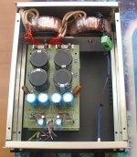
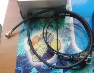
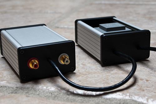
Well, I just built myself a VSPS using Wima FKP2 for RIAA capacitors, metal film resistors, Wima MKP-X2 as coupling capacitors and NE5532 opamps. Connectors are all Neutrik-brand. Just turned it on and listening as we speak This sounds amazing. Very neutral sounding! No hum whatsoever. I was using a DAC before and doing RIAA processing digitally. Impedance was +1MOhm - so sound was somewhat off.
But this just blows it away
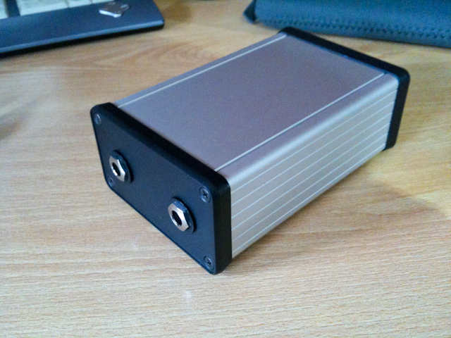
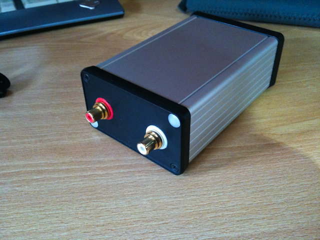
Kept it clean and small
This sounds amazing. Very neutral sounding! No hum whatsoever. I was using a DAC before and doing RIAA processing digitally. Impedance was +1MOhm - so sound was somewhat off.But this just blows it away
Kept it clean and small
Last edited:
- Home
- Source & Line
- Analogue Source
- The Phonoclone and VSPS PCB Help Desk