I use an old board, power supply with LM317/337 is more than good enough..
Instead of electrolytes, for C6-C7 use 1uF Wima MKS.. they are close to opamp and there is no oscillation, so there was no need to parallel it with faster ceramic..
That is using your board, looking at Richard's board there is no C6-C7.
Where would you put ceramic caps?
I do have a pair of AD797 and it sounds good a bit dark, I did have a OPA134, and that sounded good. I am using a really cheap cart, and will change it to an AT440 this evening.
That's right..That is using your board..
It is old VSPS board, phono part schematic is same, only different power part.. I have much more confidence using LM317/337 than X-reg.. and C6-C7 are on ideal position..
AD797 is much better opamp than OPA134..
That is using your board, looking at Richard's board there is no C6-C7.
Where would you put ceramic caps?
I do have a pair of AD797 and it sounds good a bit dark, I did have a OPA134, and that sounded good. I am using a really cheap cart, and will change it to an AT440 this evening.
It's an version I made some years back, a single channel version of the stereo VSPS with LM317/337 instead of LM7812/7912.
There is no explicit location for ceramic bypass caps, but these can be added to any board by soldering them at the op amp pins, or across the leads of nearby electrolytic capacitors.
What vulejov did was replace the 100 uF electrolytics with 1 uF film caps, which work at higher operating frequencies so fulfill the role of bypass caps to an extent. The relatively high inductance of metallised plastic film capacitors compared to ceramic/tantalum types means they are not usually recommended for this role however.
The most recent version of the stereo VSPS has pads on the board for bypass capacitors.
Anyway, I'd say trust your own ears on this... and believe me when I say the AD797 is not ideal for the VSPS MM circuit normally. Vulejov can get away with it because a) he knows what he wants and b) he's modified the VSPS circuit appropriately.
I have much more confidence using LM317/337 than X-reg.
Voltage regulators are just op amps, with a voltage reference and pass element added. The X-reg is to the LM317 what the AD797 is to the OPA134.
This is not true..The X-reg is to the LM317 what the AD797 is to the OPA134.
X-reg performance depend on the quality of the used electrolytes..
bad electrolyte-poor filtration..
Voltage stability depends on the input voltage.. inaccurate input voltage-output voltage imprecise..
So, maybe is X but not regulator..
Role of ceramic bypass is to prevent oscillation of the opamp..What vulejov did was replace the 100 uF electrolytics with 1 uF film caps, which work at higher operating frequencies so fulfill the role of bypass caps to an extent. The relatively high inductance of metallised plastic film capacitors compared to ceramic/tantalum types means they are not usually recommended for this role however.
If there is no oscillation bypass capacitor is unnecessary.. MKT doing this job expected good..
Most believe their ears more than measurements and facts.. because of that hifi is cesspool of electronics..
So we should listen to something that measures good but sounds lousy? Wow, I guess I'm really dumb...I'll just go and enjoy my music now on my crappy single-ended tube amp that measures poorly.
Such thing does not exist..So we should listen to something that measures good but sounds lousy..
But there are many who do not know what is faithful sound reproduction..
Such thing does not exist..
Of course it does...
X-reg performance depend on the quality of the used electrolytes..
bad electrolyte-poor filtration..
As any other regulator or filter (Including 317)...
This is not true..
X-reg uses a lot of capacitors because it is the only way to reduce ripple..
Voltage regulation practically does not exist.. change secondaries voltage of transformer and the output voltage will change..
With stabilizers that all you despise because of ignorance that is not the case.. voltage after them is actually filtered and stabilized..
You are correct about the stabilization part. Although I do not know how important it is. The caps make sure that it is not invasive during normal operation. I have played with +-10 up to +-12V and the difference was not that big. And I guess it is something that could be easily fixed if we replaced the voltage divider with a low noise reference assembly of some sort, although we would have to add its amplified noise to the equation.
About the ripple part, it is not true. It uses the opamp's PSRR, a very low noise voltage as basis resulting to low noise output, and the X configuration works as some sort of extra common mode rejection thingy that creates really symmetrical plus and minus voltages, impedances, phases etc, something that the LM317/LM337 pair can only dream of (and there is proof for that in this forum).
If you want to keep using 3leg parts, go for either floating dual LM317 , or dual LM337 (has better impedance and phase characteristics), or go for dual LT1085
Anyway... Back to work...
But there are many who do not know what is faithful sound reproduction..
This is not true..
X-reg uses a lot of capacitors because it is the only way to reduce ripple..
Voltage regulation practically does not exist.. change secondaries voltage of transformer and the output voltage will change..
With stabilizers that all you despise because of ignorance that is not the case.. voltage after them is actually filtered and stabilized..
OK, the issue of what is faithful sound reproduction and what most closely reflects what our ears (and brain) hear is an issue for a MUCH different forum than this.
As for the voltage regulation issue... Maybe I don't understand what you're saying. I'm pretty sure the output of a voltage regulator like the LM317 depends on the ratio between the adjust and output pins and the resistors associated with them and not the input voltage (so long as it is within spec). Meaning if my mains voltage fluctuates a few volts it won't matter if I'm using a voltage regulator like LM317 properly.
Wrong? If so, please direct me to some articles that will educate me.
Edit: Ah, truth be told, even my second question probably isn't ideal in this forum. Sorry Richard. Can't help but ask.
Hmmm, its been a while since I changed them over, and my memory being rubbish, its hard to say.
Smoother than the BoM, more detail (in a good way) even handed over all frequencies.
Put it this way, I have finished tinkering with the PC3, and the only way I think I will get any improvement is to get a Urika inside my LP12
Thanks Mr. Onion for the info.
Cheers
Hi Richard and all here. It is good to see everyone is plugging along. Richard, the last time we talked I was sending a VSPS along to Mapleshade Records to evaluate for possible sale. They had me build the unit without a buffer stage and were real specific on how they wanted it done. No metal chassis and built on wood (breadboard) and able to be put into there own solid maple chassis if they market it. Pierre has had my VSPS for close to 4 months and and as a couple of weeks ago not even evaluated it. I am trying to get it back. Built the way they asked it sounded much better than my single transformer VSPS.
I have a B-board question. If I build the b-board as a stand alone pre-amp would I use the volume control before or after the b-board? Is a 100k volume control ok or should I stick to 50K? If it goes after the board 10K should be good I assume. I am asking because I plan on building a SET 45 tube amp from tubelab and although there is plenty of gain a buffer or preamp could sound better. They want a 10K or 25K pot before the input tube at most. I may just put the B-Board in a separate box with input switching
Walr
Last edited:
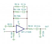
A few thoughts and questions about the high gain MC VSPS with AD797
Since we change R2 to 56R, shouldn't we also change R3 to something like 2K95 (As per Richard's Instructions) ?
And would it make sense to change the RIAA to something like
R4=1.05M
R5=7.5M
C1=100pF
C2=290pF
R3=29.5K
Trying to make the load less and have access to cheaper and better caps? Like teflon? Would the resistance noise be much higher?
Am I missing something really moronically obvious?
I know about this schmematic... It is what I am currently using with slight differences.
Any comments on what I am asking?
And what about making the caps smaller and resistors bigger? This comes from a suggestion by Thorsten on the original VSPS thread.
Any comments on what I am asking?
???Richard said:R3 2.2k Allen Wright Mod., cuts treble attenuation above 50 kHz. If you adjust R2, R3 must also be changed according to the following formula [R3 = 3000-R2], rounding to the nearest convenient value. (The exact value is not critical.)
And what about making the caps smaller and resistors bigger? This comes from a suggestion by Thorsten on the original VSPS thread.
- Home
- Source & Line
- Analogue Source
- The Phonoclone and VSPS PCB Help Desk