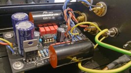
May I suggest insulating the third tab on the power switch? If it is a normally closed switch that will be a live terminal when the switch is off.
Good point, thanx! Although I haven't quite decided yet whether I'll be wiring the switch's light. But I'll definitely cover it with some heat shrink if I leave it unwired.
Nothing bad at any rate.It looks fine to me.
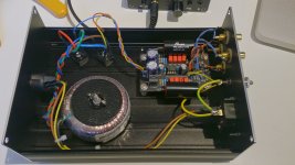
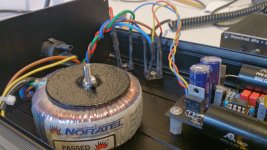
I'm just a bit concerned with having the un-shielded transformer so close to PCB, but hopefully you'll manage to get away with it.
Well, hum I definitely got...
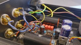
But it took 5 seconds for C5 to blow, as it was mounted backwards...

Need to get a new cap and try again. I don't think C4 got damaged. I'll lift earth too. I'll be back!...
Cap replaced, case closed (literally!)
Turns out it is dead silent!
With everything connected, turntable gnd to the vsps gnd, no hum whatsoever (well... yes, with the volume all the way up I can faintly hear *some* hum, but it is actually quieter than the background hiss)! So I didn't have to go the floating gnd way.
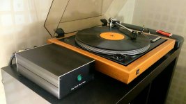
I'm really happy with this build – soundwise it compares very favorably to the pro-ject phono box it is replacing, and it puts out more volume as well. I used the MUSES8820 opamp.
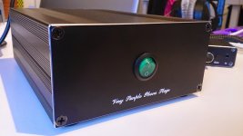
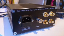
I think it turned out quite a looker as well (Front and back plates are custom made by Schaeffer in Germany). I am very pleased with all-in-one layout with the power supply on the same chassis.
Thanx Richard for your advice and for such a great kit!
PS: I ended up with gnd/com and earth all connected together to the chassis. It seems to work pretty well noisewise, as I wrote. I know I should tidy up that layout though. What would be the best way? gnd/com/earth all to one point on the chassis, like a star?
Turns out it is dead silent!
With everything connected, turntable gnd to the vsps gnd, no hum whatsoever (well... yes, with the volume all the way up I can faintly hear *some* hum, but it is actually quieter than the background hiss)! So I didn't have to go the floating gnd way.
I'm really happy with this build – soundwise it compares very favorably to the pro-ject phono box it is replacing, and it puts out more volume as well. I used the MUSES8820 opamp.
I think it turned out quite a looker as well
(Front and back plates are custom made by Schaeffer in Germany). I am very pleased with all-in-one layout with the power supply on the same chassis.Thanx Richard for your advice and for such a great kit!
PS: I ended up with gnd/com and earth all connected together to the chassis. It seems to work pretty well noisewise, as I wrote. I know I should tidy up that layout though. What would be the best way? gnd/com/earth all to one point on the chassis, like a star?
Attachments
Last edited:
Cap replaced, case closed (literally!)
Turns out it is dead silent!
SNIP
PS: I ended up with gnd/com and earth all connected together to the chassis. It seems to work pretty well noisewise, as I wrote. I know I should tidy up that layout though. What would be the best way? gnd/com/earth all to one point on the chassis, like a star?
Nice work! Dead silent usually means you did good grounding (plus some luck given the proximity of the toroid). But in general, I don't find hum to be a big issue with transformers in the same box (with occasional exceptions for very small signals like a cartridge output).
Re: grounding, in general, all grounds should end up at a star point as you suggest (so that different grounds aren't shared until the last possible moment, close to outside of the chassis). And that star point should be as close to the IEC ground tab as possible (to minimize the overlap of different signals that eventually DOES occur). Many people use one of the bolts that holds the IEC in place as the ideal star ground location.
Be scrupulous with twisted pairs for EVERY circuit connection.
Adding a screen around the twisted pairs will help a bit.
BUT most of all, you MUST filter every cable pair that enters the screening Chassis at the Chassis entry aperture.
You may be able to use your mobile phone as an interference generator.
Get your landline to repeatedly phone your mobile while you try injecting signal from every angle and at every cable entry.
Can anyone give a better method of injecting RF interference?
Last edited:
After I posted my question it dawned on me to search the tread for this kind of discussion. ;-) I want a truly dual mono design. Then I'll go full hog and use two toroids. Other than being inexperienced, my main constraint is my budget.
I have found Talema 62072 35VA and Triad Magnetics VPT24-2080 50VA trafos for practically the same price. The agony of choice...
Does the price and manufacturer have much bearing on the quality of a transformer?
I have found Talema 62072 35VA and Triad Magnetics VPT24-2080 50VA trafos for practically the same price. The agony of choice...
Does the price and manufacturer have much bearing on the quality of a transformer?
Yes in principle but no, not at this level. Both are fine.
Typical newbie mistake: progress slows to a crawl as you search about each and every variable for each and every part.
Advice: "Just go and build the damn thing already!" Then you mod or tweak and see what makes a difference, what the difference is, and then you incorporate that knowledge into what you do the next time round, and so on.
No one gets it right the first time.
The VSPS kit was delivered on Monday. Thank you Richard!
I have assembled the dual trafo PSU. It's mounted in a tin of Belgian cookies.
I'm fresh out of cigar boxes and whiskey crates...
I use a Denon DL 160 cart, and to up the gain I have replaced R2 with 220R metal film resistors.
I'm thinking of replacing C3 with 2.2uF Mundorf Supreme - Parts Connexion is just 5 minutes away from my house.
Time to get soldering.
Cheers,
Martin
Isn't Hammond Manufacturing somewhere nearby also? You could hit them up for some cases.
The gain-setting resistance R2 in the Phonoclone is set too high for the cartridge.
Use the calculator in the BOM and adjust R2 and R1 accordingly.
R2 should be about 400 ohms. That should give clean operation with both those cartridges.
I did use the calculator and for the AT33PTGII I get R1 = 10R / R2 = 333R
For the Denon 103R - R1 = 14R / R2 = 560R
Unless I use the incorrect R1 & R2 input figures I did not get the 400R you mentioned.
- Home
- Source & Line
- Analogue Source
- The Phonoclone and VSPS PCB Help Desk