source or subsitute for GBPC 602-E4/51GI-ND
Hello Im new here, I just ordered the VSPS kit from Richard and I am planning on building the standard power supply as shown in his Construction Guide. I am looking for an alternative source for the GBPC 602-E4/51GI-ND Bridge Rectifiers since Mouser and Digikey seem to be out of stock. Or is there a suitable substitute that i can use?
Also does anyone have a photo of how they have executed the build? since I am new to this sort of thing Photos are very helpful. I have been scouring this forum for the last few days and I have not come across any photos of the power supply.
Thanks
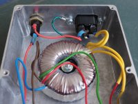
Check out my power supply. Post 1637 & 1638. Page 164.
Last edited:
GBPC5010-G Comchip Technology | 641-1383-ND | DigiKey
I used these as I wanted a guick connect type connection.
I used these as I wanted a guick connect type connection.
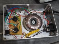
Not bad. The rectifiers have mounting holes, so you could have bolted them directly to the chassis rather than used the perf board. Other than that, pretty standard.
But:
I feel obliged to order you to immediately cover all the exposed terminals with either line live or line neutral voltages applied to them with electrical tape or, preferably, heat shrink. I mean at the IEC socket and fuse. Leaving them exposed like that is a big no-no: as well as making you look like a complete noob it also runs the very real risk of turning you into a dead noob.
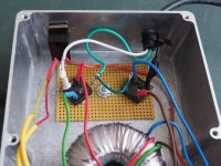
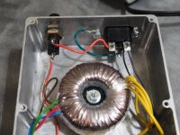
Very good, I feel safer from here.
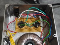
If you want to be fully up to code, you need to add a serrated washer at the earth, between the bolt head and the chassis.
The only other thing I might suggest is moving the red wire connecting from fuse to switch to the other side of the case away from the output wires.
If you want to be fully up to code, you need to add a serrated washer at the earth, between the bolt head and the chassis.
The only other thing I might suggest is moving the red wire connecting from fuse to switch to the other side of the case away from the output wires.
Very good, I feel safer from here.
If you want to be fully up to code, you need to add a serrated washer at the earth, between the bolt head and the chassis.
The only other thing I might suggest is moving the red wire connecting from fuse to switch to the other side of the case away from the output wires.
If possible, I'd even suggest swapping the switch and the outlet so that all of the raw AC supply stays on one side (side that the mains input is on) and the rectified output is on the other side. So you'd move the red wire as Richard suggests, but also have the switch on the same side. That helps avoid any coupling of the raw AC signal and the output, not that at this point in the circuit there'd be a BIG improvement, but it's good practice.
I use 2.2 uF 63 V LOT OF 2 RUSSIAN PETP AUDIO CAPACITORS K73-16 ?73-16 | eBay Bargain price, and fantastic sound.
Hi Mr onion,
The Russian capacitor looks interesting, can you describe the characteristic of the sound ?
I am using obligato gold at the moment, great cap, the sound is not analytical but very balance, wondering if I could put it to another level
Regards
Hmmm, its been a while since I changed them over, and my memory being rubbish, its hard to say.
Smoother than the BoM, more detail (in a good way) even handed over all frequencies.
Put it this way, I have finished tinkering with the PC3, and the only way I think I will get any improvement is to get a Urika inside my LP12
Smoother than the BoM, more detail (in a good way) even handed over all frequencies.
Put it this way, I have finished tinkering with the PC3, and the only way I think I will get any improvement is to get a Urika inside my LP12
- Home
- Source & Line
- Analogue Source
- The Phonoclone and VSPS PCB Help Desk