David, my turntable plinth can´t acommodate anything... It´s a VPI prime, so It´s pretty solid.
Bill, I´ll see what I can do! Just one more question (for the time): I see on the diagram that there´s a ground connection on the node comming out of the SG4´s GND and looking online I´ve found out that this symbol is for earth ground, right?
How can I earth ground that node since I´m using a 24v DC power supply?
So I gotta connect the Sleeve from the 12V DC plug to the GND of the SG4 board?
On the diagram you uploaded on page 5 there´s no such connection so that´s why I´m confused. The only DC ground on such diagram is from the DC 24v power adaptor connected to the TDA amp.
This separate safety ground could be achieved with a ground wire (with ring crimp terminals) running from a screw from the SAMA housing to a ground pin of a grounded unused outlet?
So I gotta connect the Sleeve from the 12V DC plug to the GND of the SG4 board?
No, the 2.1mm socket for the 12VDC supply on the SG4 has it's own ground connection. The ground pins by the 0°, 90°, 120° and 240° pins are the same connection as this DC ground and are to facilitate easy connection to (possibly) a number of amps.
On the diagram you uploaded on page 5 there´s no such connection so that´s why I´m confused. The only DC ground on such diagram is from the DC 24v power adaptor connected to the TDA amp.
The diagram on page 5 is not a full schematic; it is an interconnect diagram showing how to connect the SG4 to the TDA amp and how to connect the amp to the transformers. The SG4 needs 12VDC supplied on the 2.1mm socket.
This separate safety ground could be achieved with a ground wire (with ring crimp terminals) running from a screw from the SAMA housing to a ground pin of a grounded unused outlet?
Yes.
can the turntable motor be turned off via a seprate switch
hi there boyz,
Hers a odd question, ref: turning the motor on/off-- if i wanted to stop the platter rotation so as to put on/take off record, and wanted a conveinent placement of a switch to do this (it hurts my back to bend down and do it at the controller: )
)
Could i put a simple switch in the 0 v (earth?) line along with the other 3 wires that supply the phases to the motor, such that when i flick the convienently located switch the motor stops/start ?--(but i dont want to damage the motor or controller doing this?)
kind regards
Johnny
hi there boyz,
Hers a odd question, ref: turning the motor on/off-- if i wanted to stop the platter rotation so as to put on/take off record, and wanted a conveinent placement of a switch to do this (it hurts my back to bend down and do it at the controller:
)Could i put a simple switch in the 0 v (earth?) line along with the other 3 wires that supply the phases to the motor, such that when i flick the convienently located switch the motor stops/start ?--(but i dont want to damage the motor or controller doing this?)
kind regards
Johnny
Johnny, I'm considering the same thing but I don't know if it will work.
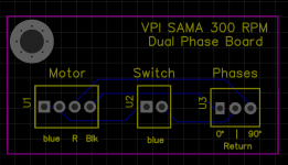
I'm trying to make a small PCB to replace the Capacitor PCB inside the SAMA housing and I came up with the attached PCB image. I'm doing this so I can avoid cutting the original leads.
One doubt that I have is if this wiring will result on a clockwise or counter-clockwise rotation.
The wiring diagram from the hurst website says that I'd need to connect the blue and red leads to the power input, and with a capacitor between black and red leads... but it doesn't say anything about running the motor on a dual phase configuration.
Attachments
OSH Park magnetic switch PCB question
hi sirs,
Sorry to bother, think my brain/eyes are on the way out??,
try as i might i cannot find the value of R1 the surface mount resistor on the Osh Park Mafnetic switch PCB?, cpold any kind soul point me to the link as i must have missed it (most likemlooking on the wrong forum
my thanks
johnny
hi sirs,
Sorry to bother, think my brain/eyes are on the way out??,
try as i might i cannot find the value of R1 the surface mount resistor on the Osh Park Mafnetic switch PCB?, cpold any kind soul point me to the link as i must have missed it (most likemlooking on the wrong forum
my thanks
johnny
I pulled (careful desoldering) a 1k smd resistor off an old CDROM drive board and reused it. Just curious to see it work, I didn't buy nor solder those 5V zener diodes, it still worked fine with the Arduino. I also can't easily find or buy the connector socket from where I live, so I soldered thin and flexible 2 core with shield patch cable the lead cable direct to the pcb. All worked fine. I will complete it later with all the required parts when I get them.
Hi everybody,
Dumb question here:
How do I know how many phases my motor have?
My TT is an Avid Ingenium, motor is 115V/60Hz.
BTW, thanks to all of you guys who contribute with the DIY community, special thanks to Pyramid, who kindly brought up the SG4 and Tachometer to us.
Dumb question here:
How do I know how many phases my motor have?
My TT is an Avid Ingenium, motor is 115V/60Hz.
BTW, thanks to all of you guys who contribute with the DIY community, special thanks to Pyramid, who kindly brought up the SG4 and Tachometer to us.
Dear Pyramid,
I have just received the TDA-7492 power amplifier and am ready to start building the project.
According to your schematic for the Lenco motor I will need Amgis L01-6362 output transformer.
As it will be hard to find this exact transformer where I live and having in mind that I have a torroidal transformer manufacturer near my office I would kindly like to ask you to confirm the specification of the transformer needed before I purchase:
1 x 220 volts primary winding (220 volts mains grid here in Bulgaria).
2 x 12 volts secondary windings.
25 voltampers.
Thank you very much in advance for your help.
1 x 220 volts primary winding (220 volts mains grid here in Bulgaria).
2 x 12 volts secondary windings.
25 voltampers.
Those specs match the Amgis xfmr and should work OK. You could also use a dual primary (115V x2) in series.
Amp question
Greetings,
I'm just getting ready to start this project. First let me thank you, Bill, for the great design and all the time you've spent helping get it up and running.
It appears that the original MK154 amp is no longer available. There are many other LM3886 amps available. Do you recommend a replacement of the TDA7492 amp that you mentioned quite a bit earlier in the thread (page 5, I think). It is still available for purchase.
Since I'm asking questions, I'll show my ignorance. The Lenco uses a shaded pole induction motor. I understand this to be a single phase motor and would not use the dual phase option that the VPI motor can use. Is this correct?
Thank you.
It appears that the original MK154 amp is no longer available. There are many other LM3886 amps available. Do you recommend a replacement of the TDA7492 amp that you mentioned quite a bit earlier in the thread (page 5, I think). It is still available for purchase.
I like the class D TDA7492 solution better than the LM3886. It generates almost no heat and works just as well if not better.
The Lenco uses a shaded pole induction motor. I understand this to be a single phase motor and would not use the dual phase option that the VPI motor can use. Is this correct?
Correct. You would use only one output transformer and connect the outputs of the amp in parallel (each low voltage secondary winding is connected to one channel L & R). Be sure to observe the polarity markings on the xfmr (each "dot" goes to positive output of the amp).
- Home
- Source & Line
- Analogue Source
- 60 WPC Amplifier for DIY Turntable Motor Drive