Ok, here is a story I am going to share with you guys for your entertainment.
Finally got a board done and decided to light it up.
So sure that I paid every attention to part orientation and detail that I would have a working board.
I was so confident in myself, that I even decided that I could plug in the SG4 chip.
So, it did not work, surprise right?
So then I decided maybe you should follow instructions and do the voltage checks in the instructions.
Pulled out the volt meter and guess what, the battery is weak.
I live out in a rural area, so the closest store is a Quik Trip.
After a 8 mile drive to get a new battery, I can see by my measurements something is REALLY wrong.
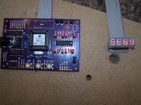
Looking over my board with a magnifying glass, I had the U5 chip 180 out, sweet.
So my question is, do I have anything salvageable, or did I blow the whole project.
Finally got a board done and decided to light it up.
So sure that I paid every attention to part orientation and detail that I would have a working board.
I was so confident in myself, that I even decided that I could plug in the SG4 chip.
So, it did not work, surprise right?
So then I decided maybe you should follow instructions and do the voltage checks in the instructions.
Pulled out the volt meter and guess what, the battery is weak.
I live out in a rural area, so the closest store is a Quik Trip.
After a 8 mile drive to get a new battery, I can see by my measurements something is REALLY wrong.
Looking over my board with a magnifying glass, I had the U5 chip 180 out, sweet.
So my question is, do I have anything salvageable, or did I blow the whole project.
Thanks, Everything else is correct.
I removed the U5 chip and have the correct voltage on pin 16 of U3.
Ordered a complete kit from mouser as I have another board.
Learning curve for me, a little different than soldering speaker crossovers.
Oh well, found out that you would not want me for your neurosurgeon.
I removed the U5 chip and have the correct voltage on pin 16 of U3.
Ordered a complete kit from mouser as I have another board.
Learning curve for me, a little different than soldering speaker crossovers.
Oh well, found out that you would not want me for your neurosurgeon.
I received the TDA7492 Class D amp from e-Bay yesterday:
TDA-7492 50WPC Class D Amp
The PCB is 3" x 2.5", about the same size as the SG4. I connected the outputs to an Amgis L01-6362 12V toroid transformer and powered the amp using a GST60A24 24VDC 60W wall adapter. To drive the toroid output to 120VAC no load, you will need to reduce the output of the SG4 to 920mVPP using a pot or a fixed voltage divider of 8.2K and 1.8K resistors.
Below are the schematics for single phase 115 and 230VAC outputs as well as a picture of the supply powering a 19W Lenco motor. The TDA-7492 PCB comes with its own heat sink, and because it is Class D, requires no additional heatsinking (the temp topped out at ~100°F after 1 hour.
The amp was $10, the wall adapter to power it was $18 and the toroid is $25.
Be sure to observe the polarity markings on the transformer and the TDA-7492 outputs.
OMG, Thank you. Exactly what I was looking for to run my Lenco L75!!!
Setting up for a Rega 24v motor
Hi,
I've just finished the board and everything is working as intended. I am using the class D amp suggested and the dual phase outputs 0 and 90.The question is: with a tester in AC mode, probing the outputs of the amp, the voltage are higher than the needed 24 volts, so I adjusted the voltage output from the SG4 down until I obtained 24volts ac at the amp outputs, is this the right way to do it?
Regards,
Jorge
Jorge-
The output of the amps will be at full voltage during motor start up, the reduced voltage that you set with the SG4 adjustment will only happen after ~5 seconds. You should use a pot between the SG4 and the input to the amps so the maximum never exceeds 24VAC. The reduced voltage after 5 secs will lower the vibration in the motor and can be 16-19VAC.
The output of the amps will be at full voltage during motor start up, the reduced voltage that you set with the SG4 adjustment will only happen after ~5 seconds. You should use a pot between the SG4 and the input to the amps so the maximum never exceeds 24VAC. The reduced voltage after 5 secs will lower the vibration in the motor and can be 16-19VAC.
Pot wiring
Hi Pyramid, thanks for your response, I appreciate...
Could you be so kind to make a drawing how to wire the pot using 0 and 90 degree outputs from th SG4? I know there is an example for the pot, but in that example, you only use the 0 degree output.
Again thank you and best regards...
P.S. Right now the turntable is working and it's in 33.3 exactly all times....
Jorge-
The output of the amps will be at full voltage during motor start up, the reduced voltage that you set with the SG4 adjustment will only happen after ~5 seconds. You should use a pot between the SG4 and the input to the amps so the maximum never exceeds 24VAC. The reduced voltage after 5 secs will lower the vibration in the motor and can be 16-19VAC.
Hi Pyramid, thanks for your response, I appreciate...
Could you be so kind to make a drawing how to wire the pot using 0 and 90 degree outputs from th SG4? I know there is an example for the pot, but in that example, you only use the 0 degree output.
Again thank you and best regards...
P.S. Right now the turntable is working and it's in 33.3 exactly all times....
Thanks
Hi...
Sorry I didn't see it... now it's clear...
Regards
Jorge
If you look at the first post in this thread, the last diagram shows a dual phase output using 2 pots connected to 0 and 90 deg outputs from the SG4. If you use a stereo pot, the outputs will track together when you adjust the pot.
Hi...
Sorry I didn't see it... now it's clear...
Regards
Jorge
Pyramid, did you tap the hole for the toggle switch?
Thanks, Greg
No, I used an unthreaded switch and just glued it in place.
But even if it was threaded, I would most likely drill it larger and use the supplied nuts to secure the switch.
I was just wondering as the throat depth of the switch is less than the thickness of the front plate.
Just wondering thanks
Right, if you're using a really thick front panel, then you will need to counter sink either the front for the nut or the back of the panel to bring the switch bushing out proud of the front panel. I also don't see a problem with threading the hole and screwing the switch into the front panel (just makes it more difficult to remove if you ever need to change it).
Ok almost done, Mr Pyramid, I noticed that you had removed the DC receptacle and soldered the power supply wires to the board.
I was hoping that a 90 degree plug would work but it will not.
Do the two grounding points need to be jumped when you do this?
Thanks, Greg
No, you can connect ground to either one, they are both connected to the ground plane.
- Home
- Source & Line
- Analogue Source
- 60 WPC Amplifier for DIY Turntable Motor Drive