Folks:
I am nearly done with my MK154 / rotary encoder / single phase version of the SG-4 and have two (possibly very dumb) questions:
1. Pyramid's wiring diagram indicates the need for a 10k pot between the SG-4 board and the amplifier, but most of the posted photos of finished projects don't appear to have that pot. Is it necessary and, if so, what is the procedure for adjusting the pot?
2. Some of the posted photographs show the input ground connection at the amplifier going directly to chassis ground, while other photos and Pyramid's wiring diagram show the amp's input ground connection going to the SG-4 board. I assume the amp input ground should go to the SG-4 board, but does it matter?
Thanks!
Regards,
Scott
1. Pyramid's wiring diagram indicates the need for a 10k pot between the SG-4 board and the amplifier, but most of the posted photos of finished projects don't appear to have that pot. Is it necessary and, if so, what is the procedure for adjusting the pot?
The pot controls the maximum output level of the amp and should be adjusted for 115VAC when the SG4 reduced voltage level is set to max (128). This ensures the output voltage will not clip and never exceeds 115VAC. The SG4 setting can then be reduced to the desired running voltage; this is a balance between low noise (lower voltage) and necessary torque (higher voltage).
2. Some of the posted photographs show the input ground connection at the amplifier going directly to chassis ground, while other photos and Pyramid's wiring diagram show the amp's input ground connection going to the SG-4 board. I assume the amp input ground should go to the SG-4 board, but does it matter?
The grounds are all connected to the same place electrically, but if you do not pair the input signal to the amp with a ground to the SG4 board, a ground loop condition could exist and cause stability or noise problems. Always best to provide a good signal ground between the SG4 and the amp input.
Hello! I´m from Brazil and I´m looking forward to building one of this for me. It would run a hurst 300 RPM 115 VAC 60Hz motor for a VPI table.
I´m currenlty looking for local sellers who could provide the parts needed but I´ll be ordering stuff abroad since I can´t find everything here.
I´m having some trouble finding an exact amplifier that could be shipped to Brazil (the ebay seller does not ship it here) but I did find two amplifiers on aliexpress that uses the same LM3886TF chip and could possibly be a substitute for the amplifier from Ebay. Can any of these amplifiers be modified for the desired gain drop and how could I do it?
HiFi LM3886TF Stereo Amplifier AMP Assembled Board 68W+68W 4 50W*2 / 38W*2 8 em Circuitos integrados de Componentes eletronicos & Suprimentos no AliExpress.com | Alibaba Group
LM3886 Placa Amplificador Estereo de Alta Fidelidade amp Montado (Com protecao speaker) Dual 18 26 V em Circuitos integrados de Componentes eletronicos & Suprimentos no AliExpress.com | Alibaba Group
Thanks!
Last edited:
Hello! I´m from Brazil and I´m looking forward to building one of this for me. It would run a hurst 300 RPM 115 VAC 60Hz motor for a VPI table.
I´m currenlty looking for local sellers who could provide the parts needed but I´ll be ordering stuff abroad since I can´t find everything here.
I´m having some trouble finding an exact amplifier that could be shipped to Brazil (the ebay seller does not ship it here) but I did find two amplifiers on aliexpress that uses the same LM3886TF chip and could possibly be a substitute for the amplifier from Ebay. Can any of these amplifiers be modified for the desired gain drop and how could I do it?
HiFi LM3886TF Stereo Amplifier AMP Assembled Board 68W+68W 4 50W*2 / 38W*2 8 em Circuitos integrados de Componentes eletronicos & Suprimentos no AliExpress.com | Alibaba Group
LM3886 Placa Amplificador Estereo de Alta Fidelidade amp Montado (Com protecao speaker) Dual 18 26 V em Circuitos integrados de Componentes eletronicos & Suprimentos no AliExpress.com | Alibaba Group
Thanks!
You need to identify the two resistors that control the gain of amp. On the attached simplified schematic, the gain is controlled by the 22K between pin 3 and pin 9 of the LM3886 and the 1K between pin 9 of the LM3886 and the cap to ground. The gain=1+22K/1K or 23x (27dB). You want to change the gain to ~5x (14dB). If the lower resistor is 1K, then make the upper resistor 3K9 (gain=1+3.9/1=4.9x).
Attachments
Alternative Class D amp
Hi Bill,
Major callamity!! Somewhere, somehow my TPA3116 amps and encoders have dissapeared in South Africa (C&E or Postal Service have stolen/lost them.) No trace to be found after 9 months, even after threats of retribution et al. I found these amps DC 12V-24V TPA3116D2 120Wx2 Stereo Digital Audio Power Amplifier Verstarker amp | eBay that are 2 x 120W using the TPA3116D2 chips; 2 for the price of one. Your opinion would be highly appreciated.
Regards,
Kevin
If you are driving transformers for a high voltage (115/230) AC synch motor, they should work OK. I would use them with 12V secondary xfmrs and supply 24VDC to the amps.
They are bridge output, so they would not work so well for the 3 phase BLDC motor; if you are using them to drive that type of motor, SE class D would be better.
They are bridge output, so they would not work so well for the 3 phase BLDC motor; if you are using them to drive that type of motor, SE class D would be better.
Hi Bill,
Thanks for the quick reply. They will only be used for the AC synchronous (Premotec) motors and Papst motors, with 2x12V primary to 2x115V secondary stepup toroids. I have some of the AA BLWS motors as well as the boards and components for your class-D design (as a matter of interest what heatsinks did you use on your boards?) and will start assembling those shortly. I'll get the encoders from one of the Arduino shops in SA. Only marginally more expensive, and delivery in a few days. I unfortunately can't find the BTL amps here in SA.
Regards, Kevin
P.S. Have the Arduino and magnets, just waiting for the display and sensor boards (OshPark) and can then get the Tachometer on the go.
Last edited:
...as a matter of interest what heatsinks did you use on your boards?
I CADed the PCB for heatsinks from Digikey (PN AE10816-ND) but it turned out they are not necessary (it also took a bit of machining to drill &tap holes in the heatsinks to work).
Bill, thanks for the tips on how to set the gain on the LM3886 chip.
I have a really basic question: In order to use a dual phase generator with the hurst 300 RPM motor I would need to remove the cap inside the motor housing and power it directly, right?
The TDA7492 Class D amp you mentioned back at page 5 does not need any gain adjustment or that is why it's needed to add the resistors (8.2k and 1.8k) on the SG4 output?
I do can find sellers willing to ship the exact TDA amp you used to Brazil, so I'm kind of inclined to follow that path (and also because it does not need a bigger heatsink).
In terms of performance, considering a positive answer to my first question, would it be better to drive the motor without the cap on a dual phase or it would be the same as driving it on a single phase with the cap?
Can the TDA amp drive a dual phase configuration?
And last, could a step down power supply buck module (based on a XL4015 converter) be used to get power from the 24v power adaptor and feed the SG4 board?
Thanks!
I have a really basic question: In order to use a dual phase generator with the hurst 300 RPM motor I would need to remove the cap inside the motor housing and power it directly, right?
Yes.
The TDA7492 Class D amp you mentioned back at page 5 does not need any gain adjustment or that is why it's needed to add the resistors (8.2k and 1.8k) on the SG4 output?
Correct.
In terms of performance, considering a positive answer to my first question, would it be better to drive the motor without the cap on a dual phase or it would be the same as driving it on a single phase with the cap?
You should be able to get lower vibration with dual phase drive.
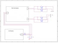
Can the TDA amp drive a dual phase configuration?
See attached diagram.
And last, could a step down power supply buck module (based on a XL4015 converter) be used to get power from the 24v power adapter and feed the SG4 board?
Should be OK, but one user had problems doing this, not sure why?
Attachments
Bill,
Thanks for the reply!
I'll look it up for the user who had issues with the step down module.
So in order to use a dual phase system I'd need to modify the VPI 300 RPM motor enclosure, removing the IEC AC inlet to install some kind of 4 pin socket? Like a XLR socket and solder the 4 wires coming out of the motor?
I see... So would I need to plug the 0° winding to the hot wire (on the IEC inlet), the 90° to the neutral and use the ground to plug the lower halves (blue wire)?
I'd need to remove the capacitor PCB and the power switch from the motor enclosure, am I right?
Two fuses would be needed, one for each winding right?
All the ground connection would be made by the ground out of the SG4 board?
I'd need to remove the capacitor PCB and the power switch from the motor enclosure, am I right?
Two fuses would be needed, one for each winding right?
All the ground connection would be made by the ground out of the SG4 board?
I've wired up a motor in the manner you described (0° to Hot, 90° to Neutral, return to Ground) for my own use, but it will violate commercial wiring codes. If you use the ground wire for the return, it should be isolated from the SAMA housing and a separate earth safety ground should be added to the SAMA housing. It shouldn't provide a safety concern if a standard IEC single phase cable is plugged into it by mistake, but it is still out of compliance (the motor won't turn as only one coil will be energized). I can't recommend that you do this and you assume the risk if you decide to do it.
The motor cap would be removed and the windings connected directly as indicated in my previous diagram.
You can use just one fuse on the common return line.
The SG4 ground plane is isolated from earth safety ground which is also isolated from any connections on the motor or SAMA housing.
Do not use and XLR connector! These are designed for low voltage and/or line level signals and could seriously damage equipment or cause injury if someone plugged the output of the amp into a piece of audio gear.
Last edited:
- Home
- Source & Line
- Analogue Source
- 60 WPC Amplifier for DIY Turntable Motor Drive