Hello all,
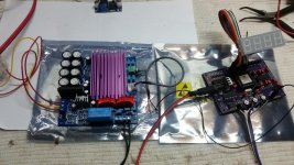
My Class D TDA8950 module arrived today. This is my first experience rigging up such a module for audio or a speed controller in this case.
I observed the following prior and after rigging it up.
1) Its got a miniature 50k stepped volume pot.
2) The onboard volume pot may be practical for audio but later measurement at the amp output revealed a slight variance in each channel after mono'ed both channels at input sourced from from SG-4.
3) I didn't have the right step up transformer on hand at this moment now, (since I wasn't sure either a 12V or 15V transformer is suitable. I used a 160VA 15V/230V transformer for test purpose connected to one side. I had to carefully crank the volume up till I saw 17V+ on the multimeter and anything beyond that, the onboard relay shut it down. I also monitored the transformer output for 230VAC maximum. The other problem was it wasn't stable, the amp started to misbehave and was unstable.The voltage wouldn't hold stable. I don't know why this happened, Its stable if the transformer is disconnected from the amp output. 2nd test was to connect the each 15V winding to each channel, the voltage wasn't present. Something wasn't right.
I don't know if the the amp have issues, insufficient voltage drive or this transformer is plain unsuitable. The transformer is not defective for sure, since its being used in a DIY PSU. Next up was a spare small 10VA 9V/230 transformer. It was stable.
4) The volume pot. I think I've to replace this to a resistor network for best results.
5) Input voltage to Amp board is 22V-0-22V (a transformer I have on hand)
6) I opened the heat sink and found questionable heat sink compound on it. I cleaned it up and applied something better that I have.
7) This amp pcb have got some blank places which I reckon is for an optional LM317/337 circuitry and +15- 0 - -15 output for some purpose. I may work on this to add a LM317 configured for 12VDC to power the SG-4 later on.
Its already got a LM7812 to power the onboard relay circuitry.
8) Second last, is the output inductor coils that are finger hot to touch, even when no load. I hope its not supposed to be like this. I could blame the 160VA transformer for this.
6) Last but not least. I found the output terminals wrongly marked. its marked as L-, L+ R-, R+. I found that L+ and R- terminals are common.
Attachments
Hello to all,
Bill,
I've just finished the SG4 board with a gain adjust board (a voltage divider using 8k2 and 1k8 just like you told me on message #136).
The readings I'm getting are, using a multimeter on VDC setting:
Stand By mode
U3 and Ground = 4.93V
U2 and Ground = 7.80 V
Both U3 and U2 values remains the same when on 60 Hz operation
SG4 Output = 2.43 V
After gain adjust board:
0° - R - 437 mV
90° - L - 440 mV
When in 60 Hz mode:
SG4 Output = 2.45 V
0° - R - 440 mV
90° - L - 444 mV
Now I don't know wich voltage my Multimeter measures in Vpp, VRMS and Vp but assuming it is similar to Peak voltage, the outupt is the double, right?
If I'm correct, than I'm getting 880 mVpp and 888 mVpp for R and L channels, respectively, both values under the 920mVPP that you told me on post #136. Should I change the resistors or it is ok to run it a little under like this?
Thanks!
You DVM will read in VRMS when set to AC volts.
Leave the 8K2 and 1K8 resistors in the circuit for now. What you are interested in is the voltage on the output of the transformer step up. When the SG4 is set to maximum output (attenuator=128), you should see 115-120VAC at the outputs. You can adjust the running voltage for less using the attenuator of the SG4, but you don't want the initial voltage too high (at start up, the SG4 will output the maximum level). If the level is too high at start up, increase the 8K2 resistor to reduce it.
Leave the 8K2 and 1K8 resistors in the circuit for now. What you are interested in is the voltage on the output of the transformer step up. When the SG4 is set to maximum output (attenuator=128), you should see 115-120VAC at the outputs. You can adjust the running voltage for less using the attenuator of the SG4, but you don't want the initial voltage too high (at start up, the SG4 will output the maximum level). If the level is too high at start up, increase the 8K2 resistor to reduce it.
@coolmaster- What is the DC voltage reading at the outputs with no input signal?
DC offset is about 98-100mV DC on each output.
Its my short sight I missed noticing the output is reversed on one side as per TDA8950 datasheet. I'm convinced the PCB marking is correct.
I'm also not sure if I should choose to use a 12V or 15V output transformer step up transformer. With past TDA 7293 build (Nigel's design), 15V output to 230V worked very well. The output from Nigel's XR2206 generator was outputting almost identical output voltage approximately from RMS 0.9 to 1.78vDC and amplifier output from 8.5 to 17.8vDC. Maximum output from transformer is around 235VAC. That generator output voltage will vary slightly depending on XR2206 quality or batch.
I'm now determined to build the 2 phase output model.
DC offset is about 98-100mV DC on each output.
That seems rather high. The output transformer will look like a direct short to ground at DC, so that is most likely why the LPF coils are getting hot. Check the output offset when the input to the amp is shorted to ground. The SG4 output is at 2.5VDC; if the input caps on the amp are polarized, they be oriented for a lower input DC offset (+ side to amp, - side to input).
15VAC secondaries should be OK for the output xfmr, but it requires about 51VPP to work properly. Class D amps are more sensitive to clipping and overload, they will go into protect mode more easily. It may also be detecting the excess DC current because of the output offset.
Which motor is this for? If you have a Lenco, dual phase does not apply.
Hi Bill,
Done some mods to the amp board. Removed the 50k volume pot and fitted a 10k 15 turn trimmer pot in its place paralleled to both channels. I output to a small 9V to 230V transformer, adjusted to max out at 230V. The amp output read at 11 volts. The output LPF coils are still finger hot. Lastly, I intend to scope later on to see the waveform.
Meanwhile I've also activated LM317 circuitry at the PCB where these components are left blank and can be used to power the SG-4 later on. This board does have this option (intended for LM317/337) but left blank with bias resistors for 15V, but I've replaced them for 12VDC. A good thing here.
The intended dual phase will be for my VPI Classic Hurst AC Synchronous motor. I believe its the same one you had worked on not too long ago, except for the voltage input difference which is 230V/50hz version for my region.
I think this TDA8950 module is suitable for implementation, pray it hold out and not misbehave earlier. I'm going to subject this to more tests.
Last edited:
Late night development.
I've got this TDA8950 amp to work and will power up the output step up transformer after some experimentation. It will now fire up test 160VA/15V/230V transformer with 15V winding connected in parallel to full output at 230VAC/50hz. Amp output voltage is 16.8VAC. Its looking good with no sign of unusual temperature rise and LPF coils now finger warm. Main heatsink is also finger warm. No load dc offset is near zero at BTL connection but still 100mV at each individual channel. The main change was the windings are connected to the amp as if in BTL mode. If each winding is connected to each channel, it simply won't fire up and its like a short circuit. However, each channel will output half the current voltage and only work with smaller VA transformers like the 9V/230 type earlier.
Connected in BTL mode, it seems there's no difference whether I jumper the board for SE or BTL. The only way this transformer will build full output is to connect in BTL mode at the output. At this time, I seem to realise this is a perplexing amp module.
Next test is to scope the output waveform and apply a motor load. I think I'll defer the 2 phase idea considering this TDA8950 module is a problematic specimen.
I'm now waiting for another TDA7498 amp module to arrive and I shall see what gives. I've decided to use a 12V transformer instead of 15V type.
Late night development.
I've got this TDA8950 amp to work and will power up the output step up transformer after some experimentation. It will now fire up test 160VA/15V/230V transformer with 15V winding connected in parallel to full output at 230VAC/50hz. Amp output voltage is 16.8VAC. Its looking good with no sign of unusual temperature rise and LPF coils now finger warm. Main heatsink is also finger warm. No load dc offset is near zero at BTL connection but still 100mV at each individual channel. The main change was the windings are connected to the amp as if in BTL mode. If each winding is connected to each channel, it simply won't fire up and its like a short circuit. However, each channel will output half the current voltage and only work with smaller VA transformers like the 9V/230 type earlier.
Connected in BTL mode, it seems there's no difference whether I jumper the board for SE or BTL. The only way this transformer will build full output is to connect in BTL mode at the output. At this time, I seem to realise this is a perplexing amp module.
Next test is to scope the output waveform and apply a motor load. I think I'll defer the 2 phase idea considering this TDA8950 module is a problematic specimen.
I'm now waiting for another TDA7498 amp module to arrive and I shall see what gives. I've decided to use a 12V transformer instead of 15V type.
If running as BTL amp, the outputs will need to be 180° out of phase (maybe this is why they were labeled strangely, or maybe there are input circuits to invert one of the channels?).
In order to drive a 15VAC secondary to create 230VAC on the primary, you will need a minimum of 18VAC. Also, 160VA is total overkill and will have higher losses and higher startup current than an appropriately sized (25VA) xfmr. A 12VAC secondary will require ~15VAC for 230VAC output.
This 160VA transformer is merely for test purposes and will not be used. I will proceed to buy a 12V type of much smaller size as you've suggested.
I stand corrected but my tracing doesn't show any of the inputs are inverted. There's 2 sets of input terminals, one is L&R,common ground the other is separate channel L&R but the negatives seem to be common too. The difference being the 3 terminal input is through the pot, the 4 terminal input bypass the volume pot. Lastly, I'm worried about the LPF coils a bit too warm for my liking. I may have to do something about this to lower the inductance (self wind another) and enlarge the size.
I have to say the SG-4 board is working flawlessly throughout this period! (I've already assembled two, the other for a buddy who's anxiously waiting for a successful outcome of this project).
Thank you Bill.
Lee
Last edited:
Hello Bill,
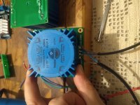
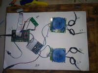
I'm getting 14 and 14.2 VAC after the TDA but nothing after the transformers. It's a pair of Talema's 70062K 25 Va 115/12 V and I think I've wired them as the picture you sent me on #136. Dots with Dots, non Dots with non Dots, both in and out of them. I get short circuits everywhere.
They came with a mounting PCB each, but different ones. I got the dots markings on the transformers by looking at the PCB printing.
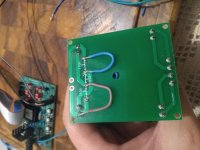
The pcb with the wire jumpers has only two holes as original AC Input (used here as output) but after soldering the jumpers (the damaged hole was an accident while trying to remove a first attempt jumper) , both holes are shorted.
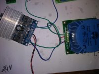
The last picture shows how I'm wiring the transformer to the TDA. Green is Negative and Blue is Positive. That also resulted on a short circuit.
One possibly very dumb question: Each transformer has 4 sets of two plugs. Is it normal for each plug to be shorted with the second one from each pair?
I don't know what I'm doing wrong, could you please help me? Thanks!
I'm getting 14 and 14.2 VAC after the TDA but nothing after the transformers. It's a pair of Talema's 70062K 25 Va 115/12 V and I think I've wired them as the picture you sent me on #136. Dots with Dots, non Dots with non Dots, both in and out of them. I get short circuits everywhere.
They came with a mounting PCB each, but different ones. I got the dots markings on the transformers by looking at the PCB printing.
The pcb with the wire jumpers has only two holes as original AC Input (used here as output) but after soldering the jumpers (the damaged hole was an accident while trying to remove a first attempt jumper) , both holes are shorted.
The last picture shows how I'm wiring the transformer to the TDA. Green is Negative and Blue is Positive. That also resulted on a short circuit.
One possibly very dumb question: Each transformer has 4 sets of two plugs. Is it normal for each plug to be shorted with the second one from each pair?
I don't know what I'm doing wrong, could you please help me? Thanks!
Attachments
Last edited:
It's difficult to tell what you are doing; you have 3 different arrangements and I can't tell what is connected in each one. Pick one transformer & PCB combo and let's stick with that to troubleshoot.
Your first picture definitely looks wrong. You have 2 cables connected to the 115V outputs, but each wire from a cable goes one side of each winding. Again, I don't know what your cables are connected to. If you are connecting the output to one of the motor windings, then use only one cable and connect the blue and white wires as shown in the attached drawing.
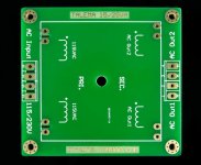
The 4th picture looks OK for 115VAC output. This will drive one winding of the motor, not both. If you drive the Blue and Green wire with one output channel of the TDA amp, it will produce 115VAC on the HV side of the PCB.
Each xfmr has 4 windings; 2 primary (high voltage) and 2 secondary (low voltage). Each winding has 2 pins, in pairs close to each other. You will read very low resistance between any two pairs of pins, especially the low voltage secondary windings will be a fraction of an ohm. This is normal.
If you can follow the schematic in post 136, it should work as drawn. Maybe someone local can assist you with the connections? If you are not comfortable working with high voltage, please seek competent technical help, otherwise you risk personal injury to yourself and damage to the equipment.
Your first picture definitely looks wrong. You have 2 cables connected to the 115V outputs, but each wire from a cable goes one side of each winding. Again, I don't know what your cables are connected to. If you are connecting the output to one of the motor windings, then use only one cable and connect the blue and white wires as shown in the attached drawing.
The 4th picture looks OK for 115VAC output. This will drive one winding of the motor, not both. If you drive the Blue and Green wire with one output channel of the TDA amp, it will produce 115VAC on the HV side of the PCB.
Each xfmr has 4 windings; 2 primary (high voltage) and 2 secondary (low voltage). Each winding has 2 pins, in pairs close to each other. You will read very low resistance between any two pairs of pins, especially the low voltage secondary windings will be a fraction of an ohm. This is normal.
If you can follow the schematic in post 136, it should work as drawn. Maybe someone local can assist you with the connections? If you are not comfortable working with high voltage, please seek competent technical help, otherwise you risk personal injury to yourself and damage to the equipment.
Attachments
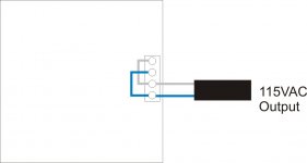
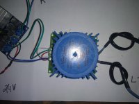
This is what one channel should look like when properly wired. The red and blue wires on the left are 115VAC output and will drive one winding of the motor. The capacitor across the output is .22uFd 400VAC film capacitor.
The Black and White wires are the 12VAC secondary of the transformer and are driven by the output of the amp.
The Black and White wires are the 12VAC secondary of the transformer and are driven by the output of the amp.
Attachments
Hi Bill, thanks for the reply.
Sorry for the bad pictures. Here are better ones that shows what I'm trying to do:
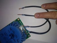
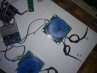
The first one shows a whole view of the cables coming out of the transformer. They're two wire cables, with one end twisted into one and the other one connecting the HV pins of the transformer, 1&3 and 2&4. I wired it to be the same as the other transformer (picture #4 on previous post).
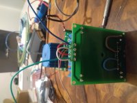
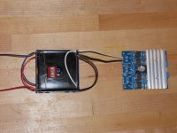
The second one shows a complete view of the testing setup, on a dual phase 115 VAC. I did not connect the motor, as I was trying to get AC voltage readings from a multimeter at the output wires. What I understood from your previous posts, R+ and L+ are each one a Phase for the motor, and the Gr and Gl should be wired together to form the Return. I tought that this way would make the transformer capacitors not necessary.
Without the transformers connected, I get 14v readings from the TDA outputs. With the transformers connected, I get 0v.
I also get 0v from each pair R+ Gr and L+ Gl.
Sorry for the bad pictures. Here are better ones that shows what I'm trying to do:
The first one shows a whole view of the cables coming out of the transformer. They're two wire cables, with one end twisted into one and the other one connecting the HV pins of the transformer, 1&3 and 2&4. I wired it to be the same as the other transformer (picture #4 on previous post).
The second one shows a complete view of the testing setup, on a dual phase 115 VAC. I did not connect the motor, as I was trying to get AC voltage readings from a multimeter at the output wires. What I understood from your previous posts, R+ and L+ are each one a Phase for the motor, and the Gr and Gl should be wired together to form the Return. I tought that this way would make the transformer capacitors not necessary.
Without the transformers connected, I get 14v readings from the TDA outputs. With the transformers connected, I get 0v.
I also get 0v from each pair R+ Gr and L+ Gl.
Attachments
Hello again to all,
I've received the basic TDA7498 (not "E" model) module from China. For what I paid for, I see its crudely assembled that reveal poor soldering and general assembly, but the thing works nevertheless. Its just me I had to perfect and rework certain areas to ensure it works reliably and looks better. Most importantly, the TDA chip is properly heatsinked (I changed the compound) and will perform consistently at high output. This module comes with a 10kohm volume pot as opposed to the other one at 50Kohm (that's when things started to get awry).
I ran this module at 32VDC supply, connected it to the test 160VA/15V transformer on one channel, signal from SG4 and it register 230VAC. DC offset register below 30mV with no load. The LPF coils is barely warm at this point, which is a good thing compared to the TDA8950 which is now a worry (but it works!) I'm continuing to put this TDA7498 module through its paces and in stereo mode later on. I shall see how this goes.
Meanwhile, I'm still very enthusiastic about implementing the TDA8950 board and undecided if I should buy another new module or replace the TDA8950 chip which I can easily buy from a local reputable vendor delivered within 4 days. We all fear that there's always the element of fake stuff or under-performing products at too good to be true prices out of China. I really need to build this project with high quality and most reliable performance.
Attachments
Bill,
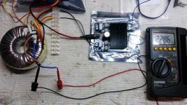
I had time to make some tests today before work and this is what I´ve found out:
1) The transformers and wiring are ok. I tested them on the AC outlet of my house (120V) and got a 14V on the other side;
2) The TDA outputs 14v with nothing connected;
3) The TDA stops (failsafe/shutdown mode)? working If I short the output and I need to reset it to start working again;
4) If I connect the DOT with the positive and the non dot with the negative outputs from the TDA, it gets shorted and goes into shutdown mode.;
5) If I connect the DOT with the negative and the non dot with the positive outputs (as the attached picture) from the TDA, it works. I get 118VAC and 119VAC from each transformer.
If this last configuration is the only way to make it work, then I would need to use the non-dots output (118VAC and 119 VAC) from each transformer as a phase to the motor (red and black Hurst wires) and wire the dots output from both transformers together to make the return wire to the motor (blue hurst wires) ?
I also removed the TDA´s heatsink, cleaned the original thermal paste and applied a better one.
Attachments
If this last configuration is the only way to make it work, then I would need to use the non-dots output (118VAC and 119 VAC) from each transformer as a phase to the motor (red and black Hurst wires) and wire the dots output from both transformers together to make the return wire to the motor (blue hurst wires) ?
It shouldn't matter whether the dot end of the windings goes to plus or minus on the amp, as long as both dot ends are connected together in parallel and both xfmr dots go to plus or both go to minus (do not mix). Likewise, it won't matter if the output dot end is connected to motor red or return as long as both phases are connected the same, that is, both dot ends connected to motor returns (blue) or both dot ends connected to motor hot (red/black).
Also, you cannot connect the xfmr to the amp while it is running (output is 14VAC). When it exits standby, the SG4 ramps up the voltage to prevent the start up current surge from shutting down the amp. If connected at full voltage, the amp will most likely shut down.
Ok, got it. I´m gonna set up a long test and if everything is good, I´ll start working on the final chassis build.
I still don´t get why the 4) does not work and the 5) does... I´ll make more tests.
I never connect or disconnect any wire from the transformers anything is on. I had both DC adapters on a extension cord and everytime I would connect or disconnect anything, I switch them both off.
I still don´t get why the 4) does not work and the 5) does... I´ll make more tests.
I never connect or disconnect any wire from the transformers anything is on. I had both DC adapters on a extension cord and everytime I would connect or disconnect anything, I switch them both off.
- Home
- Source & Line
- Analogue Source
- 60 WPC Amplifier for DIY Turntable Motor Drive