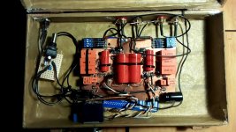
Nop it's a spare 15VA transformer/rectifiers/caps.
Here I go for 100R... BTW, that's now a very good "before I build something better" pre-phono =)
And it will possibly become even more neutral for your cartridge in your system after you experiment with the extra C3 nF. Now it already has a flat curve when the original was deviating to bright curve exacerbating your treble problem. By adding +2nF value then +4nF if not enough etc. you begin the down-tilt curve act to try counterbalance best for your cartridge's HF peak on the improperly highish Miller input capacitance for MM. The bass curve bumps up a bit also at the same time. If it will sound weird no worries, you can go back to what is already acceptable balance with 33nF alone.
 Problem solved. Finely enjoy!
still messing around with the pacific circuit..
Hey Guys,
since three years i am reading across all threats about phono preamps based on 2sk170 jfet. I have build several experimental versions of this preamp, got me a frequency generator and an oscilloscope and learned a lot of basic stuff about audio electronics. But still i am a noob and i hope you don't throw stones at me for the questions i will ask now.
I am running my pacific style preamp with an Ortofon OM10 cartridge, which is said to have 3,5 mV output at 5cm/s / 1kHz. So with most versions of the pacific that i build i run into trouble with way too much gain causing distortions on the second amplifier stage. After i run some tests to confirm where the distortion come from i decided to build another experimental version using a 50k/50k voltage divider after the riaa filter, instead of the 100k resistor, with the gate of Q2 beeing connected to the middle of the voltage divider.
I experienced a somewhat "better" sound and measurable lower distortions. Before this mod i had big amounts of THD in all orders. Now its almost only 2nd Harmonics distortion on much lower levels (like i want it to be).
But somehow i feel bad about my "solution". Can you guys explain me what happens when i run my setup with this voltage divider? What would happen if i used a 100k poti instead of the voltage divider? Whats wrong with this idea?
My circuit is very near to the "original" LePacific designs, with 5.5mA ID Jfets, but with 33R resistors to ground. My aim is to keep learning about analog circuits, thats why i try stuff that may seem wrong to experts. thanks for your answers.
Attachments
circuit drawing of my pacific version
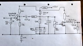
here is the circuit drawing, sorry that i did not come with it in the first place.
Its an experimental circuit, thats why Q2 does not have a source resistor but Q1 does have one of 33ohms.
So on Q1 i got around 5.5 Volts while on Q2 i have 9 Volts Vds.
I found another thread about Jfet basic questions and i guess now i could work it out to lower the gain of the jfets on both stages correctly without using the 100k poti to feed the second tranistor stage.
I am aiming for max. 28-32 dB gain on each amplifier stage.
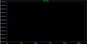
I changed the values in the riaa after reading some dubios calculation, but i still have to measure the frequency graphs of this riaa.
here is the circuit drawing, sorry that i did not come with it in the first place.
Its an experimental circuit, thats why Q2 does not have a source resistor but Q1 does have one of 33ohms.
So on Q1 i got around 5.5 Volts while on Q2 i have 9 Volts Vds.
I found another thread about Jfet basic questions and i guess now i could work it out to lower the gain of the jfets on both stages correctly without using the 100k poti to feed the second tranistor stage.
I am aiming for max. 28-32 dB gain on each amplifier stage.
I changed the values in the riaa after reading some dubios calculation, but i still have to measure the frequency graphs of this riaa.
Attachments
Last edited:
You should normally have more VDS across Q1 than across Q2 because its degenerated with 33R and pulls less current through its 2k4 drain load than Q2 which has no source resistor but same load and IDSS. Maybe you meant the voltage drops across their loads? Unless their IDSS is other than stated and differs between them too.
There's a response problem beyond no good gain allocation in that schematic. The extra high resistance you added in series to the second JFET's gate for the divider forms an RC filter with that stage's Miller capacitance and kills the last octave by 6dB more than the RIAA should. Makes a better curve with those filter parts values up to 10kHz though. Without the divider you had too much gain for MM indeed. And in the wrong place.
Put 12R to first JFET's source pin, put 56R to Q2's source pin, change Q2's drain load to 3k3. Regarding the RIAA elements add 430R to the 2k8 in series, add 5.6n to the 27n in parallel, delete the divider and use 220k in place of the original 100k from Q2's gate to ground. No extra series resistance after the 29k until the gate pin at all.
Those changes should give you prudently balanced stages for gain, 39dB total output gain considering the 20dB passive RIAA loss, a good response curve, and acceptable distortion. Lastly find experimentally a +V PSU voltage rail level that will center Q2's drain to ground voltage at half of rail. For max headroom and symmetrical clipping.
Hey Salas, thanks for your helpful answers. This weekend i applied most of the changes considering the gain stages. Q1 now has a 10R source resistor, Q2 has a 50R source resistor now. I changed the Drain R of Q2 to 3k16 because this is what i got.
To be on the safe side i used a new matched quad of 2sk170 with an Idss of around 4.6 mA, Rds is said to be 80 ohms, and Vgs is said to be -0,34V.
I have put 3nF in parallel to my 27nF. I still have to get me 400R to 600R resistors to put it in series with my 29k.
I did not have 220k resistors either, so i used 100k in the first place just to get rid of my voltage divider. Could you please explain what is the effect of setting the gate to ground resistor to 220k?
And i still have to set the right voltage bias for drain to ground of Q2.
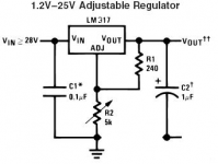
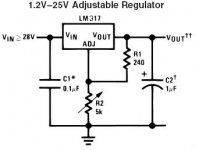
After this i will have to think about another power supply circuit because my simple lm317 circuit tends to oscillate and is very noisy..
To be on the safe side i used a new matched quad of 2sk170 with an Idss of around 4.6 mA, Rds is said to be 80 ohms, and Vgs is said to be -0,34V.
I have put 3nF in parallel to my 27nF. I still have to get me 400R to 600R resistors to put it in series with my 29k.
I did not have 220k resistors either, so i used 100k in the first place just to get rid of my voltage divider. Could you please explain what is the effect of setting the gate to ground resistor to 220k?
And i still have to set the right voltage bias for drain to ground of Q2.
After this i will have to think about another power supply circuit because my simple lm317 circuit tends to oscillate and is very noisy..
The 430R extra resistor is to make your 2.8k to 3.23k for a more accurate curve. Must put it between the 2.8k and the 99.3n capacitors, has not to do with the 29k. The 220k instead of 100k second stage's input impedance resistor helps lift your bass response a little as its an easier load for your components values before it to drive and couple to it. It was kinda shallow before but you did not notice that because last octave treble was missing also. The extra values I gave you to manipulate your now values are to be met for an excellent curve. But the closer you get with in hand components is better than nothing. Use your ears also to tune. Those values are technically correct for the modification as a whole but maybe your cartridge and loudspeakers are subjectively synergistic little otherwise.Hey Salas, thanks for your helpful answers. This weekend i applied most of the changes considering the gain stages. Q1 now has a 10R source resistor, Q2 has a 50R source resistor now. I changed the Drain R of Q2 to 3k16 because this is what i got.
To be on the safe side i used a new matched quad of 2sk170 with an Idss of around 4.6 mA, Rds is said to be 80 ohms, and Vgs is said to be -0,34V.
I have put 3nF in parallel to my 27nF. I still have to get me 400R to 600R resistors to put it in series with my 29k.
I did not have 220k resistors either, so i used 100k in the first place just to get rid of my voltage divider. Could you please explain what is the effect of setting the gate to ground resistor to 220k?
And i still have to set the right voltage bias for drain to ground of Q2.
After this i will have to think about another power supply circuit because my simple lm317 circuit tends to oscillate and is very noisy..
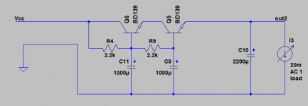
The LM317 is adjustable at least. Its should not oscillate, make sure that the chip has 100nF close and across its input. You could add a clean up capacitance multiplier right after it that in practice does as good or better job for noise than highly esteemed super low noise linear reg chips. Which are surface mount most usually meant for powering digital and very few offer high enough rail range for your purposes. Here's a two stage multiplier I devised for you. It will also put your 2200uF rail capacitor to better use than the simple RC you now got. Delete your 10R to the 2200u cap and use it as output cap to the multiplier. There will be some insertion voltage loss across the multiplier but nothing too serious with a few mA load like yours. 1.35V loss for 20mA pull.
Attachments
Hey Salas,
sorry, i misread your first answer considering the 430R.
I have experimented to set the gate-to-ground voltage of Q2 to 1/2 of the supply voltage. I ended up using 11,80V supply voltage with a Vgs of 5,60V on Q2. Q1 runs on 4,18V gate-to-ground.
I checked the voltage regulator module again and found a very stupid wiring fail.. I had two different ground points that were not connected, like in the picture on the left (vjum2-false) i uploaded as attachment. After fixing it to a proper grounding my voltage regulator combined with the simple RC-Filter is dead quiet now.
Before fixing it i listened to a test disc with a dynamics test. First you hear one 1Khz tone as a reference for 0dB. I turned my volume up until the tone was subjectively very loud.
After that the other test tones follow with -80dB, - 72dB, -66dB, -62dB, -58dB, -54dB and so on.
Before fixing my voltage regulator, i could bearly hear the -54dB tone because the background noise of my preamp was louder then the signal.
After fixing the grounding on the voltage regulator i did not hear any background noise and i could hear the test tone at -66dB very clearly.
Conclusion: My background noise went down from much more then -54dB to much less then -66dB.
But at the end of the day i tend to build a capacitance multiplier like you proposed. Thanks for the circuit")
sorry, i misread your first answer considering the 430R.
I have experimented to set the gate-to-ground voltage of Q2 to 1/2 of the supply voltage. I ended up using 11,80V supply voltage with a Vgs of 5,60V on Q2. Q1 runs on 4,18V gate-to-ground.
I checked the voltage regulator module again and found a very stupid wiring fail.. I had two different ground points that were not connected, like in the picture on the left (vjum2-false) i uploaded as attachment. After fixing it to a proper grounding my voltage regulator combined with the simple RC-Filter is dead quiet now.
Before fixing it i listened to a test disc with a dynamics test. First you hear one 1Khz tone as a reference for 0dB. I turned my volume up until the tone was subjectively very loud.
After that the other test tones follow with -80dB, - 72dB, -66dB, -62dB, -58dB, -54dB and so on.
Before fixing my voltage regulator, i could bearly hear the -54dB tone because the background noise of my preamp was louder then the signal.
After fixing the grounding on the voltage regulator i did not hear any background noise and i could hear the test tone at -66dB very clearly.
Conclusion: My background noise went down from much more then -54dB to much less then -66dB.
But at the end of the day i tend to build a capacitance multiplier like you proposed. Thanks for the circuit
Attachments
Hi
Not its gate to ground voltage, its drain to ground voltage to set at 1/2 rail's value is the goal. Nice about debugging the wiring error around your LM317. Add a 10uF electrolytic across the R2 trimmer to enhance that chip's ripple rejection 7dB further. The capacitance multiplier I proposed to you filters incoming noise very well and has extremely low self noise. Valuable, such phono circuits don't reject any noise coming from the rail, but even more valuable in MC versions where the gain is much higher.
Not its gate to ground voltage, its drain to ground voltage to set at 1/2 rail's value is the goal. Nice about debugging the wiring error around your LM317. Add a 10uF electrolytic across the R2 trimmer to enhance that chip's ripple rejection 7dB further. The capacitance multiplier I proposed to you filters incoming noise very well and has extremely low self noise. Valuable, such phono circuits don't reject any noise coming from the rail, but even more valuable in MC versions where the gain is much higher.
Attachments
Hi Salas, sorry for my messy post.. I measured the drain-ground voltage like you said, but wrote about Vgs.
So my drain-to-ground voltage in Q2 is 5,60V while my supply voltage is set to 11,80V.
I might try using the proposed 10uf electrolytic cap across the trimmer.
What is your opinion about gate stoppers to lower distortions caused to sharp s-sounds?
I fear my Pacific style circuit leads me to buy a better cartridge with a finer stylus... I
Last edited:
Because its an MM build you could try 100 Ohm direct on the gate of Q1. It will not have an impact with its self noise since the cartridge has over three times its impedance and swamps it. But your "S" thing can also be linked to you still got a highish treble plateau in the curve until that extra 3n you added // 27n will be a 5.6n as recommended. K170BL could run more current in Q2 position than GR with its now source resistor, thus drop more across its load and allow higher Vcc for centering to more output voltage headroom. Pops and clicks on records can transiently clip. Cartridge upgrade tendencies are an indication you already had done some positive fixes to your build and it moves closer to correct
P.S. For relatively economic better MM cartridge than your Ortofon OM10 see Nagaoka
P.S. For relatively economic better MM cartridge than your Ortofon OM10 see Nagaoka
Thanks for your answer, i love the idea to put a BL grade to my second stage, because i got several matched pairs and quads of GRs and BLs that i sourced for this project. I got some with 8,3mA Idss and some with 9,2mA Idss. I will try to calculate it on my own and come back with the results which Idss would fit best for an up to 22V Vcc.
When i listened to a very worn out and noisy pink floyd record i realised the increased impacct of pops and clicks now.
thanks for the hint regarding Nagaoka, [it looks like i could only use MP100 and MP110 with this RIAA, because MP150 and up want to see less then 150pf of capacitance..] EDIT i just realised that MP100 and MP110 are also running with a kind of moving iron concept, yeah
The concept of moving iron sounds so interesting
Last edited:
Its also you had no last octave treble response before when with the voltage divider in front of the second stage that rounded off the transients. Now you will discern RIAA curve tweaks and better tracking cartridges much easier. You can't go wrong with the MP110... Nagaoka MP 110 Cartridge Reviews - The Vinyl Engine
Hi Salas and guys, yew I am back, yes I have a problem. Is DIYAudio based in Houston ?!
So I've messed up my linear supply, shorted 10.000uF when all circuits on...
For ref.:
Shorted smoothing caps. Need confirmation guys!
That was a recycled gyrator but seems current/voltage drop for following LM317 was all but ideal.
So I have questions for people good in phono and supply. Sorry my greek friend
How much current needed for the Pacific we've made?
How about a LM317@22V in the remote supply case and then a LM317@18V in the phono box? I have these parts and more left, many caps and resistors, any simple supply you can recommend Salas?
I swear if I get rich I'll go BiB, Folded phono and DL110. For real!
Thanks guys!
Your build should be pulling about 12mA per channel. I would recommend you put an LM317 in the remote supply and the post's #71 cascade capacitor multiplier in the phono box. Just using a second LM317 isn't going to improve the chip's intrinsic random noise level, its iterated, just the ripple rejection. The Cmult is going to drop some little voltage in accordance to current drawn so you trim the remote 317 until you will see 18V at the output of the Cmult when loaded.
- Status
- This old topic is closed. If you want to reopen this topic, contact a moderator using the "Report Post" button.
- Home
- Source & Line
- Analogue Source
- Pacific RIAA phono pre: failure!