I am using RCz regulation ( res,Cap,Zener) for my phono stage which uses a 2SC1815 as opposed to Jfet for lower noise. My treble cut is less then yours and I have no problem with "S" sibalance or distortion. You may have an oscillation problem in one or both stages.
A 100 to 150 ohm source resistor may solve this problem.
A 100 to 150 ohm source resistor may solve this problem.
Hey guys,
i come back thinking about my gain stages in my pacific style phono. With my last configuration i had only 4.15 V Vds on the first 2sk170 with a Vcc of 11.8V. When you think about 5mV @ 1kHz one might think that should be enough headroom. My gain at the first stage is about 30 dB, so 5mV input signal will give 158mV Output signal swing. 158mV Output vs. 8V "Headroom" is 34dB Headroom in my quick calculation, that seems well enough.
But a 20kHz signal played from vinyl comes with +20dB in respect to the 1kHz signal, thats why we build this fancy preamps. So its up to 50mV input Signal @ 20kHz, thats about 1.58V Output signal after Q1. With a "voltage Headroom" Vds*2 = 8V our Headroom is down to 14 dB !
A 50mV input signal @ 20 khz also causes measurable distortion in my configuration with a Vds of only 4.15 V on the first gain stage.
This frequency-dependent distortion problem does not appear on the second gain stage, because all frequencies arrive at the same low level after the RIAA filter.
So the next aim will be to balance Vds of Q1 and Q2 to a higher level and to use maximum VCC. After some calculation i think about switching the Q2s to BL Grade with 8.6mA Idss that i have on my bench. I would have to change Rd back to 2k4 or even 2k.
i guess i finally understood ohms law, how to bias a jfet and how to calculate the drain resistor needed. Daily business for you - awkward complex stuff to understand for me...
I soldered BL-grade 2sk170s to my q2 position with an Rs of 50R. After that i measured the voltage drop through the drain resistor of 3k16. With my actual Vcc of 16V, Rd was dropping almost 12 Volts. 12V / 3160R = 0.0037 A eg. 3,7mA ID on Q2. Is this way of calculation correct?
If i want to balance the dc conditions of Q1 and Q2 i would start with measuring Q1s ID with Rs= 10R. It is 8V / 2400R in my case = 0.0033 A. After that i would select my biggest possible Vcc of 21V, my desired Vds is 1/2Vcc = 10.5V.
If i want a 10.5V drop through my drain resistor of Q1 i would calculate 10.5V / 0.0033A = 3181R .
After that i would want to set q2 to the same dc condition, calculated: 10.5V / Id Q2 0.0037 = 2838R .
Now i got my values for my drain resistors to achieve the same Vds on both of my different biased gain stages. Am i correct?
Adapting those changes would rise my headroom from 14dB to 22 dB @ 20kHz for Q1. My Headroom on Q1 for all frequencies would rise from 20dB to 30dB with those changes.
After all the maths i understand why most advanced versions of the pacific aim for a Vcc of around 36V, because of the enhanced headroom.
okay i guess i was right about my dc-point balancing calculations, but totally wrong about my headroom assumptions.
I applied all my changes because i had 2k8 and 3k16 resistors at hand to try it out. DC Voltage balancing worked very well. But what i did not consider was that gain was also rising (on Q1 to 33dB). That results in a stronger output especially after the first stage, where 20kHz frequencies are amplified from 240 mV to 11 Volts (with lots of measurable distortion), shrinking my headroom on the first stage from 14dB before the changes to 6 dB.
So i will start calculating again to
A 5mV cart at 5cm/sec 1kHz will do 50mV at 20kHz on 20dB records pre-emphasis assuming there is same potential musical groove content there. Now lets think 18dB above nominal as are the highest test records torture tracks that make most needle profiles skip. 5mV+18dB=5x8=40mV=113mV pk-pk. Very unlikely in music but lets think that there are pops and clicks in every less than pristine state record that will be the real offenders. If you will drop the first stage's gain too much the noise will go up.
Thanks Salas for both of your helpful answers. If I measure my device with an input of a sine wave of 20khz with 160 mV pk-pk the distortion drastically decreases compared to an input signal of 240mV.
If we assume 160 mV pk-to-pk to be the absolut maximum output (despite of clicks and pops) my headroom calculation gives me at least 10dB Headroom @ 20 kHz.
Would you consider this as an acceptable value for practical listening?
Is it a better solution to run both jfets with matched dc conditions or is it okay to have 8Vds on Q1 and 4Vds on Q2 like in my first version?
")
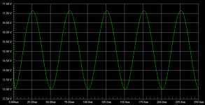
I run a sim for you and I see circa 4Vpk-pk at 20kHz at the output node of a 29.65dB gain fist stage. Driven from a 5mV (1kHz nominal) cart simulation fed through a RIAA pre-emphasis network. Biased at little above 15Vdc you can see the swing around that point. 8Vdc bias allows for double that swing...
Attachments
Hey Salas, i soldered another quick version on perfboard after i fiddled my p2p version to death. I picked 3k16 for Rd for the input stage transistor and 2k8 for the output stage. Now i have 10.4 Vds on Q1 and 10.6 Vds on Q2. My Vcc is tuned to 21.4V.
I took some smaller 100nF caps that measured 99.x nF plus one 33nF cap for my filter stage. For coupling i took simple wima mks caps using values of 0.33 and 3.3 uF.
It worked fine from the first try and almost matched my calculations (i thought Q1s Id would be a bit higher, so that Vds would have been 9V instead of 10.4V with my Rd of 3k16 and a Vcc of 21.4V). I can change the jfets pretty fast now because i used sockets. Overall it is a much more solid build then my first point-to-point version. It hass less and smaller parts and i start to realise why consumer stuff is not build with fancy 400V coupling caps ;-)
I measured frequency response using my oscilloscope, a test record and my new nagaoka mp110 cart ;-) It measured pretty "flat" from 20 Hz to 16 khz. With 20 khz there was a noticeable drop of signal (can't measure it exactly)
Right now i am listening to some of my favourite records and i like the warm sound of my phono preamp. I also like the sound of the nagaoka cart, it seems more "dry" compared to my ortofon om10 which i used before. The ortofon cart has spikes in bass and treble, while the nagaoka cart seems to have a very flat response in the mids.
I "measured" resonance peaks at 6 kHz and 8 kHz and a noticeable dropped signal after 16 khz in combination with this Preamp.
That's all very nice, congrats. To really measure the circuit's response build an anti-riaa filter and use the lab generator for signals. MM carts can show a drop in the very highs beyond a resonance region. Also test records can be dubious in the very highs. See: Load the Magnets!!! - [English]
Hey Salas,
thanks for the link, i already know this article and itvis very interesting. Thats why i had variable input resistance on my last version and my next Version will have it too.
When i measure using my signal generator the preamp measures very flat, but still with a slight drop on the higher frequencies above 18 kHz.
What i dont understand is how you calculated the RIAA values you proposed me. When i look for calculators online i find formulas where C1:C2 should be 3.6 and R1:R2 should be 11.7 or so.
With your proposed RIAA parts values i get C1:C2 = ~3 and R1:R2 = ~9.8
When i believe online calculators one oft the corner frequencies is 1550 Hz instead of 2200 Hz.
What do I get wrong here? I believe you know what you are proposing after working with this kind of RIAA preamp for +10 Years...
Have a great day
Its not after formulas its including the input stage's source resistance and the output stage's Miller capacitance in a total circuit simulation with the signal source fed trough an inverse RIAA* network. When you change something like the stages gain or the load resistors or the source resistors there are small effects happening in the curve also. The real JFET parts may differ a little from the Spice models as well. Then there are tolerances in the real passive parts. The proposed tweaks were a patch to your post #68 circuit based on its existing values for putting it into a better curve. They did their job very well for the most part it seems.
*Jung-Lipshitz standard type without a "missing constant" 3.18uS addition
*Jung-Lipshitz standard type without a "missing constant" 3.18uS addition
Thanks, i am learning a lot. I guessed that you put some other factors inside your RIAA Calculation.
How big is the impact of changing source or drain resistors on Q1 and Q2? Is it like "1%" or more like "10%" alteration of the RIAA curve? (I know its more complex but i need a guess value..)
At which point should i start to recalculate the values of the RIAA filter?
How big is the impact of changing source or drain resistors on Q1 and Q2? Is it like "1%" or more like "10%" alteration of the RIAA curve? (I know its more complex but i need a guess value..)
At which point should i start to recalculate the values of the RIAA filter?
- Status
- This old topic is closed. If you want to reopen this topic, contact a moderator using the "Report Post" button.
- Home
- Source & Line
- Analogue Source
- Pacific RIAA phono pre: failure!