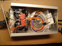
and here is my external power box.
on the right is the input EMI filter (in the plastic bag), a toroidal transformer with 2x24V, full bridge rectifier made with FFPF04N60S2 from Fairchild, followed by two inductors and output caps 10mF+3.3uF.
no-load voltage is 38V.
No, I haven't connected it to the boards just to see what happens ;-) I'll leave that for monday when I have current-limited lab power supplies....
Attachments
boards are full - power up planned for monday ;-)
this is with LCR caps, Dale resistors, and as good a matching as I could get. Input transistors are matched to 0.7% between all of them, the rest less... Its probably required to order 200...300pcs of each transistor type to get a perfect matching.....
So nice, and if you make an enclosure with an acrylic top you could read the daily news in green light (the men at the ATL would like that)
")
Cool, and I can be a bit more specific on that. Once (a long time ago) I worked for Motorola, HP and International Rectifier (among others) as an industrial 'components in-design specialist', working with our customers helping with their designs (at the customer’s site) mostly do select components to fit them to their specific environment. I have done planes, trains and automobiles (among others, including the particle accelerator in Cern
thats pretty much what I do right now for a living.... sadly enough, most of the power stuff nowadays is switchmode, not linear, it's like a lost art. and so most of the power devices are actually designed for switching, no longer for linear....
So nice, and if you make an enclosure with an acrylic top you could read the daily news in green light (the men at the ATL would like that)
cool idea!
thank you for the flowers!
not sure about the best options though.... the PNPs had consistently higher beta than the NPNs, and in all current mirrors the transistors are matched to each other pretty well (<1%) but not to the other side.... I was just too excited to move forward and didnt want to wait for more transistors - also, its not sure I would get a better fit then... so I expect to do some finetuning.
the next footprint will include 10k trimmers next to the 120ohm resistors... this will be difficult....
Hi there
I am going to get same sleep now
60 hours at my day Job over the next 5 Days
I have started on the proper lay out (all nice and properly line up) and 2 symmetric circuits for the pre regulator
I am changing the cap sizes to include 17 to 22.5 mm capacitor footprints
There are loads of available MKP type on those sizes from the like of Farnell and RS.
Even the radial 1839 series with a body length of 14 mm would fit nicely
If you have a preferred option just let me know.
Another thing I was thinking about if ATL approves is to try the lay out for the circuit as in post 4674 is there a corresponding negative circuit
Yes, the PNPs have higher beta and that in unusual. Normally it is the other way around.
The worse that can happen is that the DC is off. The good thing is that more forward gain in any direction can be nearly ideal compensated by adjusting the emitter resistors in the mirror in one or the other polarity. Even if some volts develop it will not destroy the circuit. What can happen is that both channels do have not the same gain so that has to be checked. If you "mistune" both channels the same that can not happen. They will simply will have the same DC offset. I ignore some minor details here that have to do with distortion but then the analysis gets complex. Ideally a perfectly matched circuit with the highest possible Hfe transistors has the least amount of third harmonic. The early voltage has an effect on the second harmonic or was that the other way around ?
Harry Haller knows.
Yummie Yummie
WOW Looking good
@ Frans, my dad was an aircraft engineer (one of the best if I may say so).
And he could not (until today) understand what the @^)#^( I like about electronics
What a great thread this is Joachim
Audiofanatic
WOW Looking good
@ Frans, my dad was an aircraft engineer (one of the best if I may say so).
And he could not (until today) understand what the @^)#^( I like about electronics
What a great thread this is Joachim
Audiofanatic
boards are full - power up planned for monday ;-)
this is with LCR caps, Dale resistors, and as good a matching as I could get. Input transistors are matched to 0.7% between all of them, the rest less... Its probably required to order 200...300pcs of each transistor type to get a perfect matching.....
Another thing I was thinking about if ATL approves is to try the lay out for the circuit as in post 4674 is there a corresponding negative circuit
After a quick consult with ATL they gave there approval, cost me a few beers though, don’t tell anyone, and do not sell the circuit. You need additional approvals to connect it to the mains, but you may hook it up to a bicycle dynamo (those ATL people do think very environmental friendly).
To create the negative (dark) side of it, replace all NPN with PNP devices and reverse the diode's.
Have fun
You will drop an additional 5 volts so you need an (about) 3.5 volts higher transformer voltage (I would go for a 5 volts higher voltage). You do not need to user a higher voltage specification in the buffer capacitors.
Regards,
Frans.
Hesener, have you matched input transistors to 0.7percent for paralelling, or also total hfe value for N to P(both sides)?
hi, yes all PNPs and NPNs fall into the same range for beta, within 0.7%. I thought that the input stage is the one that does the heavy lifting and so it should be as perfect as possible. That matching includes both channels' input stages.
Checked my notes, they are all at 520 +/- 0.3%
Last edited:
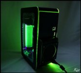
Green light is Romulan warp core. Sure you want that...?
I love it, just add the 'Area 51'-component and you know why it is Romulan.
