choices --
backing up a bit as I have been distracted from this forum --- The foil resistors by Vishey and others have been used in high end audio for a long time -- JCurl talked to me about them about a thousand (or more) years ago... Use them if you want them...and can get them and pay for them but the Dales are soooo cheap I thought they would appeal to many cash strapped DIY as a better part than typical mfr parts. They have lower thd than adc/dac [BTW -I have a QuanTec resistor analyzer.]
the 2n556__ are pretty good in matching out of the box - I used them in a design (TAA) back in the day. I see the one i used is no longer made") -()... but the others - higher volt et al are still around and so ordered a dozen just to have on hand -in case they stop making those, also. Also used the dip motorola MPQ-6 ____ for their ease and werent a bad match for compliments.... if package dissipation limites are not a problem. They are still around in some models and now with second sources. Might find a place to simplify the circuit build that has a lot of individual parts/transistors.
-()... but the others - higher volt et al are still around and so ordered a dozen just to have on hand -in case they stop making those, also. Also used the dip motorola MPQ-6 ____ for their ease and werent a bad match for compliments.... if package dissipation limites are not a problem. They are still around in some models and now with second sources. Might find a place to simplify the circuit build that has a lot of individual parts/transistors.
Maybe just do the layout for smd as many here want to use it.... and someone can do another pcb for the thru hole guys. Or they'll do it in Taiwan sooner than later and offer it on eBAY in both ways. Like they do for DAC's.
BUT -
Just make it with your suggested parts which are SW blessed - that includes transistors.... or just use what he spec'ed and Get Er Done. Or you'll have to peel those gold stars you just got from SW off your foreheads.
IMO a buffer needs to be excellent as a stand-alone design... very low thd and dc offset on its own. That way it can be used with the SW-OPA and other projects that only need current boosting/low Z driver. Same 24v rails. Though it seems the existing design can just be scaled up in the output stage so an additional buffer isnt needed for it.
I must have missed something, Its late here. Tomorrow a fourth-world family is coming to stay with me for a week in DisneyLand - (Bangkok) then to the beaches of Phuket for another week.... spoil them with love. My hope is that the girls will never want to settle for rice farming once they have seen a better life and what they can do with thier education. OOOooop. wrong forum 10-4 and out.
backing up a bit as I have been distracted from this forum --- The foil resistors by Vishey and others have been used in high end audio for a long time -- JCurl talked to me about them about a thousand (or more) years ago... Use them if you want them...and can get them and pay for them but the Dales are soooo cheap I thought they would appeal to many cash strapped DIY as a better part than typical mfr parts. They have lower thd than adc/dac [BTW -I have a QuanTec resistor analyzer.]
the 2n556__ are pretty good in matching out of the box - I used them in a design (TAA) back in the day. I see the one i used is no longer made
-()... but the others - higher volt et al are still around and so ordered a dozen just to have on hand -in case they stop making those, also. Also used the dip motorola MPQ-6 ____ for their ease and werent a bad match for compliments.... if package dissipation limites are not a problem. They are still around in some models and now with second sources. Might find a place to simplify the circuit build that has a lot of individual parts/transistors. Maybe just do the layout for smd as many here want to use it.... and someone can do another pcb for the thru hole guys. Or they'll do it in Taiwan sooner than later and offer it on eBAY in both ways. Like they do for DAC's.
BUT -
Just make it with your suggested parts which are SW blessed - that includes transistors.... or just use what he spec'ed and Get Er Done. Or you'll have to peel those gold stars you just got from SW off your foreheads.
IMO a buffer needs to be excellent as a stand-alone design... very low thd and dc offset on its own. That way it can be used with the SW-OPA and other projects that only need current boosting/low Z driver. Same 24v rails. Though it seems the existing design can just be scaled up in the output stage so an additional buffer isnt needed for it.
I must have missed something, Its late here. Tomorrow a fourth-world family is coming to stay with me for a week in DisneyLand - (Bangkok) then to the beaches of Phuket for another week.... spoil them with love. My hope is that the girls will never want to settle for rice farming once they have seen a better life and what they can do with thier education. OOOooop. wrong forum 10-4 and out.
Last edited:
My Layout version done, ready for review!!
Hello folks,
Okay, this was a fun exercise, I got the comps in a tight as I could. I usually stick with a 25mil place grid but a couple I had to move with a 10mil grid. I thought that it was going to be a nightmare but actually it was not that bad after I did an initial placement and started to connect the guides. Managed to route all but a few at 12mil, just a couple nets, I had to wick down to 8mil to get through those SOT-143B
I put VCC & VEE planes on the bottom. There is no room on top for an effect ground plane. Vias (37) @ 30 pad/16mil FHS. I'll attach some drawings, original schematic, I posted had an error.
Size is 1.225x1.0 inch. I see that the John Hardy 990 measures, 1.125” x 1.125” x 0.600”
Have some questions however!!
1) What to do about a ground plane? 3-4 layers = expensive
2) Supply decoupling?
3) Mounting footprint?
4) Need to verify the schematic I drew up?
So there you have it
Cheers Rick
Docs
See attachments, let me know what you think?
Problem with cramming this tight, is each ref position is hard to identify, no effect Silk screen text!!
See attachments, let me know what you think?
Problem with cramming this tight, is each ref position is hard to identify, no effect Silk screen text!!
Attachments
Last edited:
need ground plane. if we want to keep it neat and small, 4 layer is more expensive yes, but if we are all happy to throw in for a GB then I doubt it will be a big deal overall. As a plus it will deter at least some of the inevitable pirates from just lifting the layout
Last edited:
In a book LOW NOISE CIRCUIT DESIGN by Motchenbacher and Fitzen they compared noise among jfets. They stated that the 2n3821 had the lowest noise of any jfet they tested. Second was the 2n4416A. Motorola made a plastic version called the MPF3821 and there is existing stock of this device. Does anyone know anything about this or is the newer Hitachi/Toshiba devices even lower noise? Thanks, Ray
top assembly
Top assembly drawing.
Took me equivalent of < one working day to get this far, so it ain't hard to duplicate. Suggest to put some copyright's notices on the material, if we want to protect the information? I have not seen any copyright notices on material on this site!
Seems that all the jfet mfg's can agree on a standard pin out, in SOT23, so can substitute parts quiet easilly.
Lifting the layout, all the connections are done on the outside foil layers. The ground plane will only have connection to the low side of C4 and de-coupling. I have no de-coupling caps in this design yet!!
Attachments
Last edited:
I have a small Swedish company togheter with a friend within manufatoring of high end products.
I have good contact with a company in South Korea that manufactor and assemble our PCB for the amplifiers.
I can check prices with them bth with and without component mounting if that is interessting.
//Jonas
I have good contact with a company in South Korea that manufactor and assemble our PCB for the amplifiers.
I can check prices with them bth with and without component mounting if that is interessting.
//Jonas
In a book LOW NOISE CIRCUIT DESIGN by Motchenbacher and Fitzen they compared noise among jfets. They stated that the 2n3821 had the lowest noise of any jfet they tested. Second was the 2n4416A. Motorola made a plastic version called the MPF3821 and there is existing stock of this device. Does anyone know anything about this or is the newer Hitachi/Toshiba devices even lower noise? Thanks, Ray
Motchenbacher and Fitchen, and the later M. and Connelly are well behind the times on specific devices, albeit excellent books for basic theory. The series and parallel noise data, aka voltage and current noise data, presented graphically in the first three appendices of the 1973 book, although still relevant are very old now.
Not sure where you found the statement about the 2N3821, although M&F comment about its low gate current noise at one point. It is a small geometry device and therefore higher series noise than many.
JFET noise goes down with channel width given the same channel length. Effectively you are paralleling more devices. But parallel noise goes up, so there is a limit to the improvement. For most audio apps, but emphatically NOT condenser microphone preamps, the impedances in the circuit are relatively small, frequencies fairly low, and thus parallel noise from the FET is not a significant contribution. But capacitance goes up too. The likely best JFET for many applications available today, having low capacitance along with low voltage noise is the NXP part BF862. Low C means we can parallel more of them before the total C gets bothersome. Voltage breakdown is low so it is often best to use in a cascode to limit the drain voltage.
Toshiba makes great parts but has discontinued most of them. Linear Integrated Systems makes almost-direct replacements of some, and is working on others. There are other specialty houses like Interfet who support the nuclear science people and make good stuff as well.
Top assembly drawing.
Took me equivalent of < one working day to get this far, so it ain't hard to duplicate. Suggest to put some copyright's notices on the material, if we want to protect the information? I have not seen any copyright notices on material on this site!
Seems that all the jfet mfg's can agree on a standard pin out, in SOT23, so can substitute parts quiet easilly.
Looks like a nice job. I love how large the SOT-23 packages appear compared to the complementary duals
I have attached below an audio preamplifier that can be the basis for achieving an operational amplifier with discrete components.
All inputs are appriciated, but with all due respect this is pretty far from a broadly applicable circuit. With 1K output resistance, split feedback, and here set up for phono there would be major changes needed.
$40-50USD for standard values in 0.01%; for what you will get in exactly the custom value you want from Texas components in 0.02% for ~$10-12....
I was thinking more of pennies for the resistors.
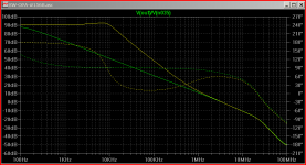
splitting the Ccomp, bootstrapping the middle to the driver output gives 30 dB more loop gain to 20 KHz; costs < 10 degrees phase margin
heck it even looks like flat loop gain to 10 kHz
from the below Ltspice sim, simple Middlebrook loop gain V souce in series with feedback divider
split Comp, doubled pF, added 500 Ohm to Q15 emitter
green trace: original single pole loop gain;
yellow: split, bootstrapped Ccomp 2-pole comp
heck it even looks like flat loop gain to 10 kHz
from the below Ltspice sim, simple Middlebrook loop gain V souce in series with feedback divider
split Comp, doubled pF, added 500 Ohm to Q15 emitter
green trace: original single pole loop gain;
yellow: split, bootstrapped Ccomp 2-pole comp
To keep the ball rolling, here's a quickie knock up of the schematic from #1568 for those who are averse to fiddling with the versions already posted. Appears to be OK, haven't checked everything, I'm sure people will point to any problems ...
The PSRR looks much, much better of course. One thing though, can't push the output standing current up to 8mA easily for some reason ...
Frank
Attachments
Last edited:
splitting the Ccomp, bootstrapping the middle to the driver output gives 30 dB more loop gain to 20 KHz; costs < 10 degrees phase margin
This is good, we tend not to use these techniques because they can effect fine scale settling. For audio this might not matter.
statistics on 19 BF862
Finally set up to screen some today off a strip and got through 19 pieces. The tempcos are all fairly small and the measurements didn't take long to settle. The bench ambient was about 75 F.
Vds was fixed at 4.00V except for the drop across a current sampling resistor in the drain of 10.0 ohms. 200 ohms was in series with the gate to prevent RF oscillations. Idss was measured, then the reverse bias on the gate to bring the current down to 100uA.
Mean value of Idss: 15.693mA. Standard deviation 1.567mA.
Mean Vgs for 100uA Id: -634.3mV. Standard deviation 43.9mV.
I also looked at Id with the gate floating (actually tied to the source through the 200 ohms and 330pF). This value corresponds to the operating point where the drain-gate leakage current is the same magnitude as the forward gate-source current. It ranged from a high of 25.2mA to a low of 17.8mA.
So, for differential applications matching is necessary. The good news is that otherwise the temperature coefficients are small.
I've been looking at settling in sim lately as a matter of course. I can't easily simulate thermals, which are there if you look hard enough, but it's interesting to see how close intuition is to what sims say.This is good, we tend not to use these techniques because they can effect fine scale settling. For audio this might not matter.
I wonder what the 990-style compensation does to settling behavior?
This is good, we tend not to use these techniques because they can effect fine scale settling. For audio this might not matter.
I would say, for audio wider flat loop gain matters more, and +30 dB on 20 kHz is a huge advantage.
- Home
- Source & Line
- Analog Line Level
- Discrete Opamp Open Design