Finally set up to screen some today off a strip and got through 19 pieces.
It's good to people willing to spend a little of their free time contributing to this.
> I wonder if anybody's interested in a parallel effort to design a dedicated unity gain follower to complement the general purpose op amp?
I already have umteen versions of those, some published and some not.
Jung diamond buffer, source follower with or without cascode, .....
Also DIP8 compatible and pin compatible with single or dual opamps on 10x10mm footprint.
You just need to tell me what you want.
Patrick
Hi Patrick,
Which one sounds best and which one is most stable with various loads?
Here is a first shot at a blow by blow description of my op-amp idea. No guarantee that it is clear to everyone so important clarifications can be added.
Hi Scott,
Thank you very much, your explanation is illuminating.
I still miss FETs and transistors part numbers.
Hi Scott,
Thank you very much, your explanation is illuminating.
I still miss FETs and transistors part numbers.
There are several possible parts lists, I think the biggest issue is the SMD vs through hole versions. Frankly most of them will make a functioning amplifer so we will have to tolerate a little indecision for a while.
There are several possible parts lists, I think the biggest issue is the SMD vs through hole versions. Frankly most of them will make a functioning amplifer so we will have to tolerate a little indecision for a while.
Okay, understood and accepted.
Mean value of Idss: 15.693mA. Standard deviation 1.567mA.
Mean Vgs for 100uA Id: -634.3mV. Standard deviation 43.9mV.
Brad: So how many should we order to get a matched pair after matching. So out of 19 units the drift is 1.567 ma. Should we consider a larger sample than 19? Of the 19 how many hit the mean Vgs within 2 %? What % precision should we shoot for? Thanks, Ray
I was thinking more of pennies for the resistors.
indeed so would I be initially. I was just countering the statement that for highest performance SMD resistors should be avoided. I wont use them for all positions. i'll build with susumu RG thin films initially till the opamps find a final resting place and a final set of operating conditions.
Once all is said and done, then i'll choose a few in critical positions in the circuit and replace with the ASMP (actually at these currents the ASM will likely do) to sooth my audio-nervosa
it might be worth narrowing down a few positions and using group purchasing power to get the price down if anyone else is interested
wider ol bw
I also agree. but a chk on the settling time affects is needed for 'due diligence.' It could limit some apps - such as, with fast converters.
I would say, for audio wider flat loop gain matters more, and +30 dB on 20 kHz is a huge advantage.
I also agree. but a chk on the settling time affects is needed for 'due diligence.' It could limit some apps - such as, with fast converters.
Last edited:
for a given spread what affect does the spread (mismatch) have on thd/harmonics of X10 amp and X100 SW-OPA? From worse case measured from the 19 pieces to tight spread of maybe 2%. I suspect it might be a small difference because of the high olg/fb available. What does sim say?
It's not clear to me yet how close they have to be matched. Gut feeling is that out of the 19 I could get two or three decent pairs. By tweaking the source resistors in the lower devices in SW's design, [edit: post 1675] one can accommodate mismatch there more readily.Mean value of Idss: 15.693mA. Standard deviation 1.567mA.
Mean Vgs for 100uA Id: -634.3mV. Standard deviation 43.9mV.
Brad: So how many should we order to get a matched pair after matching. So out of 19 units the drift is 1.567 ma. Should we consider a larger sample than 19? Of the 19 how many hit the mean Vgs within 2 %? What % precision should we shoot for? Thanks, Ray
Stay tuned. Except for the tedium and however one fixtures them for testing, at least they are cheap and widely stocked.
The general impression I get talking to others about the few remaining Toshiba parts, they tend to be more tightly distributed. The few 2SK2145 duals I tested so far were quite tightly matched. According to a friend, the singles comparable to the 2145, the 2SK117 and whatever the SMD version is are pretty tightly controlled in his experience. The 2SK2145 is not usable in the SW design owing to the hardwired connection between channels, and the transconductance is not as good as the BF862.
I noticed that the leads on the BF862 are ferromagnetic. This may disturb some, but it makes it easier to retrieve ones that go tiddly-winking out of the tweezers and onto the floor, using a permanent magnet.
I am also planning to parallel a bunch of them by soldering their gate leads to a piece of wire, which will serve as a heatsink, and seeing if the resulting assembly is sufficiently stable against oscillation to require only one gate-stopper resistor or lossy inductor. In that situation the matching among the parts need not be as tight, as the characteristics will benefit somewhat from the effect of averaging.
Brad
Last edited:
Pirates are out there! The whole idea about this is a shared design but they have another agenda. A shared design is vulnerable. The Chinese will have this built and available for sale shortly I bet. Ray
The best is always quietly stolen (sometimes not so quiet). Take it as the compliment that it is. (I'm now capable of issuing the odd 'cease and desist' order. Some of you know what that means)
As this project is definitely in the "hand carved by virgins from solid Unobtainium" class .. and as certain values need to be tweaked anyway .. why not allow presets or AOT components in strategic places and place it in an even more rarified category?
ie "hand carved and tweaked by virgins from solid Unobtainium"
The only caveat would be once tweaked, will offsets remain the same?
At least the "hand carved .. etc" buys you some concrete advantages unlike so many such projects and products.
_________________________
I've been playing with fas42's model of Guru Wurcers FET i/p 990 version from #1511.
The 990 has a similar topology to a low feedback power amp I did a lot of work on circa 1990. So I have a lot of 'real life' vs 'simulations' I can call on.
I'm using this project as "Become a LTSpice guru for Dummies". In the 90's, I spurned SPICE for my own Circuit Analysis programme ... but that was of course only linear.
I think it might be possible to get near Wurcer performance with less complexity.
There's still a lot of work to do but it appears that this is possible given that it doesn't have to be unity gain stable ... as long as a clear tweak path (caps vs noise gain) can be written .. as with Guru Wurcer's.
What can it do?
In the tested form, 10x gain 600R load
+292V/us -175V/us
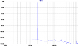
20kHz 10Vp distortion FFTs are enclosed. I'm still trying to get to grips with LTSpice. In particular, the FFT of the input waveform Vi.png seems to vary from day to day. Vo.gif shows the individual harmonics are easily -110dB.
But here I'm cheating. Both the zillion V/us and low THD are obtained by using Prof Cherry's 'inclusive' compensation. This is far more subtle than Self and even Baxandall realise. One advantage of this method is by not slowing the output of the VAS, 'crossover' is minimized. This is in direct contrast to the Gospel according to Self and others but I can vouch for its practical effectiveness.
But one caveat is that the output of the VAS (Q16) needs to be kept pristine. Vo.gif is without the clamping diode Q8 which is essential for clean overload. The slight capacitance of the diode-connected Q8 is enough to degrade the THD to Vr.gif. 2nd is now -95.5dB and 3rd -105.2dB. (Note the input FFT floor has changed yet again.) BC546 best out of 1n4148, 2n4401, 2n5501.
Suggestions on low capacitance diodes (with good SPICE models) for Q8 and also advice on how to get super low distortion sine waves in LTSpice would be appreciated.
__________________________
Incidentally, the clamp diode Q8 in Scott's & fas42 models need to use collecter/base rather than emitter/base. Emitter/base has higher capacitance and will also Zener in this position. I'm impressed that fas42's SPICE models actually reflect this capacitance (if not the Zenering)
ie "hand carved and tweaked by virgins from solid Unobtainium"
The only caveat would be once tweaked, will offsets remain the same?
At least the "hand carved .. etc" buys you some concrete advantages unlike so many such projects and products.
_________________________
I've been playing with fas42's model of Guru Wurcers FET i/p 990 version from #1511.
The 990 has a similar topology to a low feedback power amp I did a lot of work on circa 1990. So I have a lot of 'real life' vs 'simulations' I can call on.
I'm using this project as "Become a LTSpice guru for Dummies". In the 90's, I spurned SPICE for my own Circuit Analysis programme ... but that was of course only linear.
I think it might be possible to get near Wurcer performance with less complexity.
There's still a lot of work to do but it appears that this is possible given that it doesn't have to be unity gain stable ... as long as a clear tweak path (caps vs noise gain) can be written .. as with Guru Wurcer's.
What can it do?
In the tested form, 10x gain 600R load
+292V/us -175V/us
20kHz 10Vp distortion FFTs are enclosed. I'm still trying to get to grips with LTSpice. In particular, the FFT of the input waveform Vi.png seems to vary from day to day. Vo.gif shows the individual harmonics are easily -110dB.
But here I'm cheating. Both the zillion V/us and low THD are obtained by using Prof Cherry's 'inclusive' compensation. This is far more subtle than Self and even Baxandall realise. One advantage of this method is by not slowing the output of the VAS, 'crossover' is minimized. This is in direct contrast to the Gospel according to Self and others but I can vouch for its practical effectiveness.
But one caveat is that the output of the VAS (Q16) needs to be kept pristine. Vo.gif is without the clamping diode Q8 which is essential for clean overload. The slight capacitance of the diode-connected Q8 is enough to degrade the THD to Vr.gif. 2nd is now -95.5dB and 3rd -105.2dB. (Note the input FFT floor has changed yet again.) BC546 best out of 1n4148, 2n4401, 2n5501.
Suggestions on low capacitance diodes (with good SPICE models) for Q8 and also advice on how to get super low distortion sine waves in LTSpice would be appreciated.
__________________________
Incidentally, the clamp diode Q8 in Scott's & fas42 models need to use collecter/base rather than emitter/base. Emitter/base has higher capacitance and will also Zener in this position. I'm impressed that fas42's SPICE models actually reflect this capacitance (if not the Zenering)
Attachments
I wonder if anybody's interested in a parallel effort to design a dedicated unity gain follower to complement the general purpose op amp?
The (these days monolythic) commercially made ones tend to have enough bandwidth to include within an opamp's feedback loop, somewhat higher power output than the opamp of the family, and voltage gains of greater than -0.1dB. I'd guess all those could be included in a topology that has no common mode issues.
Heck, the output follower of your proposed general purpose device does most everything I'd want. It really only lacks a (guarantee-able) very low input current.
Makes me wonder if the transconductance stage and the output follower don't really want to be two separate critters. I tend to use these separately for my own poor homebrew efforts already.
Thanks,
Chris
Sounds great, propose some parameters.
The (these days monolythic) commercially made ones tend to have enough bandwidth to include within an opamp's feedback loop, somewhat higher power output than the opamp of the family, and voltage gains of greater than -0.1dB. I'd guess all those could be included in a topology that has no common mode issues.
Heck, the output follower of your proposed general purpose device does most everything I'd want. It really only lacks a (guarantee-able) very low input current.
Makes me wonder if the transconductance stage and the output follower don't really want to be two separate critters. I tend to use these separately for my own poor homebrew efforts already.
Thanks,
Chris
Your instincts are good, Richard ... as a first exploration along those lines I altered the VTO of the BF862 model to create 2 new versions, BF862.02 and BF862.03 such that cut-off Vgs was firstly -0.85, and then -0.5, giving a nice spacing of Vgs at 100uA around Scott's figures. BETA was slightly adjusted to give Idss's of 25 and 10mA, maximums per the data sheet.for a given spread what affect does the spread (mismatch) have on thd/harmonics of X10 amp and X100 SW-OPA? From worse case measured from the 19 pieces to tight spread of maybe 2%. I suspect it might be a small difference because of the high olg/fb available. What does sim say?
Into 1k load, gain of x100, 20kHz at 20Vpp the 2nd harmonic is down 89dB using the normal BF862 model. Then I tried 2 extra runs with BF862.02 on +ve input, BF862.03 on -ve; and then reversing that. Severely mismatched, so the source resistors had to be adjusted to 5 and about 75 ohms to correct offset.
The distortion only deteriorated to -86dB in the worst case ...
Frank
Last edited:
ac or dc matching?
That's as it should be... a minor difference -- 3db in this case -- for high gnfb designs.
Then, the diff pair matching might best be focused more on dc and or thermal tracking/offset considerations rather than for lowest thd/harmonics. Thx - RNM
Into 1k load, gain of x100, 20kHz at 20Vpp the 2nd harmonic is down 89dB using the normal BF862 model. Then I tried 2 extra runs with BF862.02 on +ve input, BF862.03 on -ve; and then reversing that. Severely mismatched, so the source resistors had to be adjusted to 5 and about 75 ohms to correct offset.
The distortion only deteriorated to -86dB in the worst case ...
Frank
That's as it should be... a minor difference -- 3db in this case -- for high gnfb designs.
Then, the diff pair matching might best be focused more on dc and or thermal tracking/offset considerations rather than for lowest thd/harmonics. Thx - RNM
Last edited:
Just noticed this morning another AM radio FET but dual. Someone should evaluate the matching and audio frequency noise. This could be another gem like the BF862. But the user will be punished by an even smaller package.
If you are not targeting the ultimate noise, here's a little gem from the former Sanyo (currently Onsemi) I've successfully used. About 3nV/rtHz noise (measured) and low Ciss. And an easy to solder SMD package.
Available for pennies at Digikey.
I've been away for some days; it was so nice weather that we decided to take a trip to our place at the countryside, picking fruit, making some DIY jam and chutney as well as deer hunting.
@rsavas post #1658, if you are referring to the schematic I posted with the SMT parts the emitters of Q17 are connected right in my schematic, shall be tied to OUT. Q17 can be omitted, it is not needed for the operation of the circuit, but limits the current in the OPS to about 145mA (with RE=4R7).
About matching: IMO the most important parts to match would be the IPS JFET's, the current mirror Q's BCV61 and BCV62 are good matched as they are.
BTW: Two of the remaining pins on the DIL-8, can be used for offset null.
As Mr. Cox is saying, there are different ways to do the phase compensation (instead of a conventional Ccomp) that will increase the available loop gain @ 20k. I have not focused on this so far.
@Dick post #1662, not sure if SW has blessed the Q's I'm using. I can't see any Gold Stars on my forehead, if I find one I promise to wash it off.
BTW#2: I'll be away from Wednesday till mid-November.
Stein
If you are not targeting the ultimate noise, here's a little gem from the former Sanyo (currently Onsemi) I've successfully used. About 3nV/rtHz noise (measured) and low Ciss. And an easy to solder SMD package.
Available for pennies at Digikey.
The problem I have with SMT is not that they can sound uniform. They can sound uniform, but on the wrong side of the equation. Choked, is how they sound. Uniformly choked, wide-band, under all loading, from micro to macro.
to-92 and similar is a good balance between thermal sinking and transient function. Too big and too much '3d material' can mess up field effects and their associated path-connectivity, and so on. Each has their faults and their benefits. (SMT vs the rest)
Since the ear hears via transient function, in all parameters.... micro linearity in transients, and specifically as compared to one another wide-band, in all moving and living complex harmonic function ---this becomes the critical point. (this is the part that 'few-to-none' in the audio industry understand is the primary critical function for all circuitry)
It's not just the measurement, it's signal development in the physical sense that becomes the primary function, here. Heck, it undeniably is the primary issue, here. Unavoidably so.
SMT could be good (might, as it reaches it's own stability and stays there -depends on use and execution, ie an isolated thermal bubble) for thermal tracking, but not, IMO, for primary signal development and expression. It's the nonstop 'zero to a jillion' requirements in thermal tracking stability (linear dissipation) under an onslaught of continual complex transient function that kills the SMT - right at the gate.
Last edited:
- Home
- Source & Line
- Analog Line Level
- Discrete Opamp Open Design