For the "take a +12V auxiliary line from there" How do I ID the spot on the PCB where you are talking about?
Maybe you could use your meters as power on led instead of the led, just lowering the current resistor a bit.
Maybe you could use your meters as power on led instead of the led, just lowering the current resistor a bit.
I may have to... The bummer is that I already got the illuminated power switch.
Here is the tech sheet on the power switch... It looks like it does not pull much at all...
Illuminated Power switch
The button probably contains an ordinary LED and has a built in resistor for 12 V feed. 10-30 mA would be my guess. Do you feed the power on LED with that, and kept 2k2 resistor? Then I guess it doesnt light up the house? And you could measure the current by taking the voltage drop over the 2k2 res.It looks like it does not pull much at all...
/Staffan
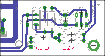
I am leaning towards hooking up both the Illuminated power switch and the VU meeter board to this spot:
I do have a heat sink coming for the 7812... I am buying a kit from Teabag. Having the heatsink on the 7812 perhaps I can push having both the Illuminate power switch and the VU meeters? Salas mentioned this 7812 is the breaking point I think...
I do have a heat sink coming for the 7812... I am buying a kit from Teabag. Having the heatsink on the 7812 perhaps I can push having both the Illuminate power switch and the VU meeters? Salas mentioned this 7812 is the breaking point I think...
To my knowledge a 7812 takes well over 1 A sinked. You see were you have gnd. Its the copper lane that connects the centerpin of 7812 and the power on LEDs cathode. Between LED and the 12 V output from 7812 output pin you have a 2k2 current limiting resistor.
Dont think the copper lanes are designed for 1 A tho, but that you wont need.
Staffan
Dont think the copper lanes are designed for 1 A tho, but that you wont need.
Staffan
Last edited:
PS - Teabag has upped the capacitors on the kits to 10,000uf 35v from 4700uf 25v... Not sure if that added capacitance changes things..
Not in this case but its a good thing for hotrodders who does 2*15 V trafos. 25 V is licking its limits there since its ripple on the ingoing rectified 21ish voltage. Sure it is 2 times 10 000 per rail? They will most likely be big.
Staffan
It will rise 20c/0.5W. I would not ask the chip for more than 500mA on that sink with circa 20V raw dc in we got here.
This is the unit I now ship with the kits.
6237BG - Board level heatsinks
Some people use non at all on the 7812. I have not heard of one blowing up.
I have updated the BOM on page 1 to reflect this. There are sometimes part substitutions as kit stock as I order it is not available.
Often if one vendor runs out, they all might.
6237BG - Board level heatsinks
Some people use non at all on the 7812. I have not heard of one blowing up.
I have updated the BOM on page 1 to reflect this. There are sometimes part substitutions as kit stock as I order it is not available.
Often if one vendor runs out, they all might.
Last edited:
Cool...
I was planning to do two sets of output using the Salas advised "100 Ohm buffer resistors Y split" This VU board has a R/L channel input...
So would I do the Y split on the two sets of RCA outputs and then run a 3rd set of outputs to this VU board I think
So I'd have for a channel output off of the DCB1 3 lines out. I'd Put 100R in line with each output RCA. Think I should run a line direct from the DBC1 to this VU board or should I put a 100R inline here to the VU as well?
A question about CCS differences due to PMOS/NMOS Vgs differences. I had less currentdraw on the negative rail on all 4 cards, as mentioned before. The relation is about the same on all cards. Putting a 56R over 10R on negative side makes about 8,4R measured and that about balanced it out. That makes a relation 8,4/10.
Do you think this relation will stay if I grill each side a bit more? I was thinking to buy some 3,3R and 4,0R caddocks, but they dont come free.
best regards
Staffan
Do you think this relation will stay if I grill each side a bit more? I was thinking to buy some 3,3R and 4,0R caddocks, but they dont come free.
best regards
Staffan
A question about CCS differences due to PMOS/NMOS Vgs differences. I had less currentdraw on the negative rail on all 4 cards, as mentioned before. The relation is about the same on all cards. Putting a 56R over 10R on negative side makes about 8,4R measured and that about balanced it out. That makes a relation 8,4/10.
Do you think this relation will stay if I grill each side a bit more? I was thinking to buy some 3,3R and 4,0R caddocks, but they dont come free.
best regards
Staffan
I beleive Salas voiced it, or deemed it to sounds better out of balance this way ---- but it may not to you.
BTW, this issue occurs in the SSLV1.1 boards as well, but there you want to correct it.
but it may not to you.
I wouldnt know, since I have not yet listened

Well, I'm working on a second hand baught malfunctioning lightspeed, thats why. Guess Ill plug'em in one day with a standard pot, but I havent yet.
Thanks
Staffan
This is the unit I now ship with the kits.
6237BG - Board level heatsinks
Some people use non at all on the 7812. I have not heard of one blowing up.
With that one I would not draw over 300mA from the 7812 for long term reliability.

To exactly balance the main CCS currents (offsetting the PMOS-NMOS Vgs dif in essence) is mostly perfectionism since the Gfs of such MOSFETs does not vary appreciably for few decades of mA dif even. But perfectionism achieved gives satisfaction and peace of mind which is a welcome factor to any hobby.
- Home
- Source & Line
- Analog Line Level
- Salas hotrodded blue DCB1 build