My design has a ferrite bead inductor with virtually zero resistance. Its just like the datasheet recommends. Moreover, the datasheet tells nothing about possible issues due to ground splitting.another circuit did not share that 10ohm 'gnd breaker' idea. but all of my 3 pga builds have had this heatup stuff happen.
That could POTENTIALLY initiate an oscillation, which is also not the case, because both times it happened to me - it happened while nobody touched inputs or outputs. But seems that you managed to detect the heat-up in time, so none of your IC went dead? I wasn't so lucky.I did swap inputs and that might have been significant.
This shouldn't be, or at least, if it's the case - it should be a repeated issue - EVERY shorting should cause the freak-out then... But it does not.perhaps shorting some inputs (1/4" trs plug siding thru the shorting metal jack) would cause it go freak out somehow? I stopped using rca plugs and have gone to stereo TRS to carry my line levels. you can't use trs's without shorting as they are just that way when you insert or remove them. this is the only thing I can think of;
and it still does not explain the freak-outs that happen all on their own (no jacks being changed).
Exactly this is what I am talking about. No visible systematic cause. My device was working just fine for a month, then died suddenly, during one night. The fact of it's random occurance makes me thinking that we have found a bug in the IC. As for me, I'm pretty sure, because even if we did something wrong, this should be explicitely stated somewhere in the datasheet or other documentation, should be at least a warning, that SUCH A CASE CAN OCCUR! For me there's nothing wrong if the chip hangs up once a month, but totally unacceptable, that such a condition can damage the device, and it's not even stated anywhere.
So far, as potential counter-measuers, I'm going to apply a CLC mains filter and better filtering for digital power rails of PGA. Also thinkin' about shorting inputs to ground when in standby.
Last edited:
sadly, I have not done enough fault isolation. ALL my builds have been mostly done just so I can do some driver development (lol) and so if the volume varied at all, my proto was good enough for me 😉 but I did do an rmaa test on one of mine and it came in as clean as the base equip (RME firewire box as the a/d and d/a). it was impressive and I was hopeful. I ran a few variants of the chip on some test hardware and lived with it for months and months. usually, it would keep working fine; but sometimes the 'overheating' thing would happen and I could hear it very clearly (shot noise and no audio) in the speaker. that would trigger me to get on my feet and yank power out 😉 I don't think I fried any chips but I certainly thought I did, many times.
I always blamed my perf board layouts or bad local bypass electros or the rail splitter (TLE) or something. I think my software was ok (lol) but I never ever trusted my own hacked up power supplies.
I do think this chip series has great potential; but I also think there's a lot more tlc needed to get it running and running *well* and I wasn't in the right stage of my project to throw lots of time at this (I went with a relay approach; for now; deferring the pga until the relay stuff was done) 😉
one of my next trials was to see if any of the packaged dc-dc's would take my nice 5v and make 2 'analog fives' from it that are clean enough (once some filtering happens) to be used. I really don't like having to supply a dual rail, especially since boxes like this are more digital control than analog and 5v rules here. I never put time into playing with those dc-dc's and filters but that would be my next move. I'm still not sure the TLE that I used was all that great of an idea.
50-Step Shunt Attenuator Resistor Calculator - Neville Roberts
and choose 32 steps , then you calculate resistors in parallel to fit in 6 relay combination .
And at the end you will find my value !
Thank you for the information Danzup.
I was further analysing your shunt circuit, but find the variance between the steps rather wide and variable. I probably missed something 😕
What I did was calculating all possible resistor combinations using your values (10, 100, 470, 4700 and 10k) for the resistors. Then I sorted them according to their attenuation factor and tried to select the interesting steps (in the beginning and the end 6 and 4 dB allowed, in the middle preferably 2 - 3 dB steps).
The thing is: I can hardly find 32 steps that are significant and usable (I'm not going to use < 1dB steps suddenly followed by a 4dB step for example..).
Attached my excel sheet with a graph showing the variance for each step called "Step(1->12)" varying up to 11dB and the total attenuation called "Att(0->70)"
Do you have a similar varying step-size?
Thanks for your help!
Berny
Attachments
Last edited:
Tone Control
Hi
This week end I finished passive preamp with tone control.
Original source code by danzup I took here
http://www.diyaudio.com/forums/anal...controlers-source-selections.html#post1907172
Thanks Dan for the original passive preamp schematic
Hi
This week end I finished passive preamp with tone control.
Original source code by danzup I took here
http://www.diyaudio.com/forums/anal...controlers-source-selections.html#post1907172
Thanks Dan for the original passive preamp schematic
Attachments


Schematic
Congratulation !
How do the passive tone controller sound ?
Mine not ready , as I am involved now in another urgent project !
I see you only connected the + dB side ... 🙂
I must find time for finishing this project .
Attachments

Last edited:


Linuxworks, don't you remember what supply did you use to power digital part of your projects?
it sounds funny, but I never cared as much; as long as the device worked at all and I was able to live with it and see my software run, I was mostly happy 😉 the focus of my work was more firmware and UI and this device was just a way to verify that things worked in reality. I hoped that I'd get time to try real pcb's (all my protos were perf or very hacked pcb) and that there would be more attention to the PSU and layout and all that. I felt that could be worked out but that my time was better spent playing in the firmware area.
I can't really say that the device has issues or its just very sensitive to 'environment' and that I knew I had a sloppy environ and so I never went beyond that to figure it out. the TLE rail splitter (I think I always used that, btw) seemed to get hot during these strange periods and I mostly thought it could be a bad use of those in this application. I never had a true bipolar PSU, I derived gnd from the TLE railsplitter chip.
I'm not really an analog guy (as you could guess) and so nothing could be implied by working or not-working on any perf version I throw together 😉 I was surprised things worked at all, to be honest.
but what I can say is: things would be fine for a long time. for days and weeks I'd use my software and this vol control chip and things sounded 'fine' to me. then, some burst of static and nothing I could do via the software would bring it out, only a power down, wait, power up. then things were fine. after a while I stopped doing firmware updates (I liked the code the way it was) and then just became a user of the device. again, weeks and weeks would go by without any problem until the static and mandatory reboot was needed.
Thank you for the information Danzup.
I was further analysing your shunt circuit, but find the variance between the steps rather wide and variable. I probably missed something
What I did was calculating all possible resistor combinations using your values (10, 100, 470, 4700 and 10k) for the resistors. Then I sorted them according to their attenuation factor and tried to select the interesting steps (in the beginning and the end 6 and 4 dB allowed, in the middle preferably 2 - 3 dB steps).
The thing is: I can hardly find 32 steps that are significant and usable (I'm not going to use < 1dB steps suddenly followed by a 4dB step for example..).
Attached my excel sheet with a graph showing the variance for each step called "Step(1->12)" varying up to 11dB and the total attenuation called "Att(0->70)"
Do you have a similar varying step-size?
I have been following this thread and trying to fully understand your spreadsheet. I understand how to calculate attenuation etc and the conclusions you reach but I dont fully understand the structure of your spredsheet ie the =(IF(D29,$D$21^-1,10^-10)+IF(E29,$E$21^-1,10^-10)+IF(F29,$F$21^-1,10^-10)+IF(G29,$G$21^-1,10^-10)+IF(H29,$H$21^-1,10^-10)+IF(I29,$I$21^-1,10^-10))^-1 etc.
Probably obvious but could you explain a bit further... this work is excellent and probably wrll overdue🙂
For each step I check how to account the resistor depending of the position of the corresponding relay. IF(logical_test,value_if_true,value_if_false) will recognize 0 as false and all other values as true. If the relay is ON = 1, the output for that if-structure is the (R)^-1 (inverse of the value). If the relay is zero, the output of the if-structure is the inverse of an infinitely big resistor ((10^10)^-1 = 10^-10). The equivalent shunt resistor is the inverse of the sum of the inverted resistor values you have in parallel. Req=((Ra^-1) + (Rb^-1) + (Rc^-1) + ...)^-1. Better values I found are: 12000, 5500, 3400, 2350, 1700 based on a photo from a commercial product, and I hope they don't mind too much... Anyway I still don't understand their solution fully and there should also be a switchable serie-R I guess.
I have been looking at good SMD resistors (thin film and bigger physical size would be better) and relays. For now I have been using G5V2 and wondering if there is something better and smaller. For the resistors I am tempted to try the SMD MELF (MMB02070C7509FB200) from Vishay / Beyschlag. Anyone a better suggestion?
Last edited:
I have been looking at good SMD resistors (thin film and bigger physical size would be better) and relays. For now I have been using G5V2 and wondering if there is something better and smaller. For the resistors I am tempted to try the SMD MELF (MMB02070C7509FB200) from Vishay / Beyschlag. Anyone a better suggestion?
Melf SMD and Takamishawa 5V relay are the best !
This is what I am using .
Melf SMD and Takamishawa 5V relay are the best !
This is what I am using .
Do you have a type-number for each?
What values do you use for your shunt attenuator and what is the step-size and number of usable steps you achieve?
Thanks for the help.
Do you have a type-number for each?
What values do you use for your shunt attenuator and what is the step-size and number of usable steps you achieve?
Thanks for the help.
Berny all the info are here in this thread :
- for r/2r attenuator I am using values identically with Jos van Eijndhoven ( http://jos.vaneijndhoven.net/relaixed/index.html )
( 64 steps as I use 6 relay )
http://www.diyaudio.com/forums/atta...olume-controlers-source-selections-dmw7pg.png
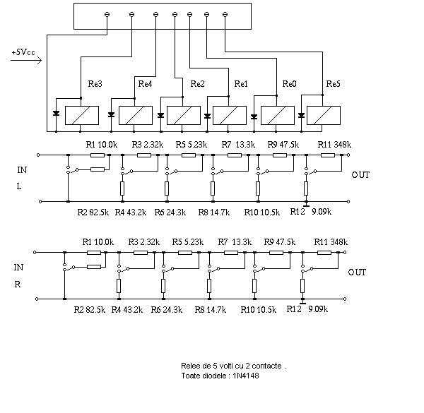
- for shunt attenuator there are some values that are result by month of using and listening by me:
( 32 steps as I have 6 relay )
http://www.diyaudio.com/forums/atta...volume-controlers-source-selections-shunt.png
and now again I have modified the values as in the attached pic and this for my audio set-up like this :
CD-Player--->Shunt ATT--->Tube amplifier--->96dB speakers
more info on first page of this thread an project number 3 with all info there .
Relay are this :
http://www.tme.eu/html/RO/relee-seria-a/ramka_1970_RO_pelny.html
Attachments

Last edited:
Hi, Dan!
Would you mind if I repost your schematics/firmwares available here on my forum in russian, if someone may ask for?
I have created a discussion thread with photos of my device and supposing that russian-only-speaking people will ask for comments, advises and schematics...
The discussion is here (though not too much helpful for non-russian speaking people)... But also people post there some very interesting "authentic russian" tube projects...and even is someone may not speak english, the schematics and photos are still talking for themselves...
Hi, Dan!
Would you mind if I repost your schematics/firmwares available here on my forum in russian, if someone may ask for?
I have created a discussion thread with photos of my device and supposing that russian-only-speaking people will ask for comments, advises and schematics...
The discussion is here (though not too much helpful for non-russian speaking people)... But also people post there some very interesting "authentic russian" tube projects...and even is someone may not speak english, the schematics and photos are still talking for themselves...
Please do so !
You are free to do what you want .
Danzup,
even if the necessary number for PCB is not achieved yet, I do have to buy some stuff anyway and could have some LCD for a reasonable price.
Is your software limited to the 2 lines x 16 characters LCD as in the BOm, or would a say 2 lines x 20/24 characters work as well ?
Cheers,
Max
even if the necessary number for PCB is not achieved yet, I do have to buy some stuff anyway and could have some LCD for a reasonable price.
Is your software limited to the 2 lines x 16 characters LCD as in the BOm, or would a say 2 lines x 20/24 characters work as well ?
Cheers,
Max
The software is not limited to 2x16 , that was used to stay low on price overall !Danzup,
even if the necessary number for PCB is not achieved yet, I do have to buy some stuff anyway and could have some LCD for a reasonable price.
Is your software limited to the 2 lines x 16 characters LCD as in the BOm, or would a say 2 lines x 20/24 characters work as well ?
Cheers,
Max
But 2x 20 or 24 also work .
I am using often 2x20 LCD.
- Home
- Source & Line
- Analog Line Level
- Yet another Volume controlers and source selections