For your simulated circuit, you should consider changing :
1) C1,2,5,6 to 10uF minimum
2) R8,16 to 10k (using 500ohm to drive a 1k load is a bad idea)
3) add caps (100uF) to gnd after R9,10,17,18
I would use a complimentary follower with a single pair of 2SK170/2SJ74 and no source degeneration. Hardly any distortion with 10k load.
Patrick
I will try all of those suggestions
Regarding 1) I thought I could lower the caps because the circuit is now seeing 1 Meg as opposed to 10k or 20k.
....
I would use a complimentary follower with a single pair of 2SK170/2SJ74 and no source degeneration. ...
It's worth noticing that such a buffer is topologicaly a push-pull and its' sound character is somewhat different. Its' input capacitance is significantly higher too. That's the price to be paid for higher drive capability...
All correct, except that before I put a 4.7n at the output of the IV stage, I am not too worried about 41p at the input of the complementary follower.
A push-pull buffer stage has less distortion and lower output impedance.
But use what you fancy. All matter of taste.
Patrick
A push-pull buffer stage has less distortion and lower output impedance.
But use what you fancy. All matter of taste.
Patrick
so biasing source at AVCC/2 (or close enough, the exact V doesnt seem to matter all that much) is no problem due t o being Vground right? for sabre users input Z really should be quite a bit lower, i'm not even sure paralleling the jfets will get us there for best DNR; but the sound is another matter I guess. I have DCB1 PCBsready and waiting for a reason and this seems like a good one, but I need to tick a few more boxes yet. BTW this would be for ackodac not buffalo II. same diff though as far as numbers that matter here.
linear systems JFETS would seem the logical choice here no?
linear systems JFETS would seem the logical choice here no?
... To use the Zen I/V Converter with a TDA1541A, do it need any modification ?....
It will work as it is but performance will be sub-optimal.
It will work as it is but performance will be sub-optimal.
That's too bad. There are lots of DIYdac's using that chip. We should focus on making it optimal, or better than resistor I/V
It will work as it is but performance will be sub-optimal.
Do you have any data on that? The manufacturer does not
mention voltage degradation in the data sheet.
Do you have any data on that? The manufacturer does not
mention voltage degradation in the data sheet.

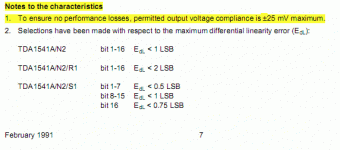
TDA1541A datasheet (page 7) says:
"Notes to the characteristics
1.To ensure no performance losses, permitted output voltage compliance is ±25 mV maximum."
I made 3 DACs with that chip, tried various I/V solutions and found out that it really sounds best with DAC's output as close to 0V as possible.
Snap from datasheet:
Attachments
Last edited:
- Home
- Amplifiers
- Pass Labs
- Zen I/V Converter
