Hi Rudolf ! I think you are a very experienced designer so i will not do a tutorial on Cepstral Analysys. There is material availlable that explains it in detail and i will try to find the article for you that you mentioned. I am more a practical guy so this is how i see it.
The Power Cepstrum is a post process on the transfer function, that is magnitude and phase over frequency. The frequency response may look rather flat for the eye but it contains small local ripples due to reflexions. This is caused by sound bouncing back from reflecting surfaces and interfering with the source. Some frequencies are partly canceled others anhanced so combfiltering ocures. In praxis it looks like ripples because there is finity measurement resoltution and damping. The Power Cepstrum shows this reflexions transfered into the time domain as a magnitude value. In my simple words i would call it an echo criterion. Now comming back to the measurements on tweeters i did
the plot looks rather clean on the OX tweeter in the first 400usec but after that is energy that looks similiar to the SEAS 19TFF1 tweeter. The only object there is, is the microphone itself. You can see on the photo that it is a stick with around 8mm diameter and 25cm length optimes for low reflexions already. This is obviously not goog enough so what we see is reflexion on the measurement microphone. Yes, this Cempstral Analysys is very powerfull and i should try to damp the microphone body and measure again.
I have now done first calculation on a reflex box for the Peerless. A 100 liter box works well tuned low. This is to compensate the rather high Qts of the driver. This is not small but managable. I think a solid bass is importand too for recunstructing "space".
I will do the system active in the bass and will use a subsonic filter under 20Hz. That way i get around 105dB soudpreasure to 50 Hz and under that the room will help. According to Martin Colloms, room gain is plus 9dB at 20Hz in a medium sized room so my alignement is -9dB at 20Hz.
I will do the system active in the bass and will use a subsonic filter under 20Hz. That way i get around 105dB soudpreasure to 50 Hz and under that the room will help. According to Martin Colloms, room gain is plus 9dB at 20Hz in a medium sized room so my alignement is -9dB at 20Hz.
Attachments
I still have questions regarding the cepstrum 
The position of the mic on the timescale is understood, but aren't the differences before 600 µs interesting too? Any impulse from the 19TFF1 would reach the front plate radius after ~140µs (4.7 cm) and generate some diffraction effect there. Is that what I see as a 150 µs peak in the SEAS plot? The OX should have an equivalent peak at ~ 50 µs (1.67 cm). This is not apparent in the OX plot. Or should I just compare the 100-250 µs plateau of the SEAS with the same (but much lower) plateau of the OX? Am I already asking too much of the method? I would have hoped that it could reveal some details of the driver's behaviour too.
BTW: I live less than an hours drive by car from your home. I wonder if I could have a sneak view of your development center some day.
Rudolf
Yes Rudolf, come by any time. I can show you only my home lab but that may be interesting too. At work i use the Klippel and a modified DAAS but it is not set up at the moment because we are in a process to launch a new company that will make very sofisticated loudspeakers. The design of the cabinets alone takes much of my time. No, they will not be ZDLs like the one i try to design here. I do that for fun in my sparetime. Give me some time to think about the interpretation of the plots. I do not want to publish some b.. s... and the interpretation needs deep thought. Yes, the time before 600usec is the most interesting. I do not find as much time for DIY recently as i had some month ago. The question is also WHY are the plots of the OX so much better and what will happen when i measure the midrange ?
I think too that the 150usec peak in the SEAS is where the frontplate ends. After the Huygens priciple this is a strong discontinuity with a full 180° phaseshift. By the way, i do not want to discount the SEAS and give it a bad name. In a conventional wide baffle it works admirably but it is simply not suited for this project.
I think too that the 150usec peak in the SEAS is where the frontplate ends. After the Huygens priciple this is a strong discontinuity with a full 180° phaseshift. By the way, i do not want to discount the SEAS and give it a bad name. In a conventional wide baffle it works admirably but it is simply not suited for this project.
I am just meditating over this :
http://www.falstad.com/ripple/
Probably one of the best visualizations out there if you want to understand wave propagation. Now translate that into a three-dimensional space

Probably one of the best visualizations out there if you want to understand wave propagation.
I have to second that. Helped me to understand wave interaction much better and debunked some myth.
Joachim,
have you found those "diffractions coming around the corner" in the ripple tank? I didn't.
In fact I don't buy Elias' explanation at all. If you look at his initial explanation, he compares a tweeter in a test baffle with the same tweeter nude. But his "diffractions" stay at the same place in time. Shouldn't they have very different times of travel for both cases?
By chance I found a source for nice tweeter housings. If you want to get stylish at last.
Rudolf
have you found those "diffractions coming around the corner" in the ripple tank?
$ 0 270 1 0 false false 8 10 668 1
s 165 31
c 48338 0
w 172 0
l 158
c 60232 0
Or were you thinking about something else?
More "sophisticated"!Or were you thinking about something else?
I was thinking of a bullet-like tweeter housing. You probably need to read Elias' post some pages ago. A crude version is this:$ 0 275 1 1 true false 8 22 668 1
s 166 133
c 40701 0
w 1 0
l 333
w 1 0
c 1 0
w 1 0
l 331
w 1 0
c 3 0
w 1 0
l 664
w 1 0
c 5 0
w 1 0
l 662
w 1 0
c 7 0
w 1 0
l 995
w 1 0
c 8 0
l 335
c 1 0
w 1 0
l 994
c 67174 0
Thanks guys for doing some experimentation. When i find the time i will follow it.
Rodolf, this housings look cool !
I will do some more measurements.
I will damp the microphone and i will damp the back of the tweeter.
If there is any roundabout effect i may see it but considering how well the responses look from the OX tweeter it must be very small.
Yes, Elias measurements did not make a lot of sense to me but it is clear, that a tweeter with a conventional round frontplate fails badly on the open air test.
 Hello Joacham,
You have me looking and thinking. This is the way this is in my mind. The goal is to have the speaker built and placed in the space in way not to give a clue to its presence.
The low frequencies have wavelengths so long a big square box can hide. The higher frequencies need softer forms to wrap around. The lower frequencies fill the room; how far away from the mids and highs can the lows be placed without appearing to be a separate source?
DT
All just for fun!
DT, i will place the crossover from woofer to midrange at around 250 Hz, maybe lower.
I have to check if the midrange gives up before the woofer. Frequencies at that point are more then a meter long so i think i can build the woofer box rather conventionally.
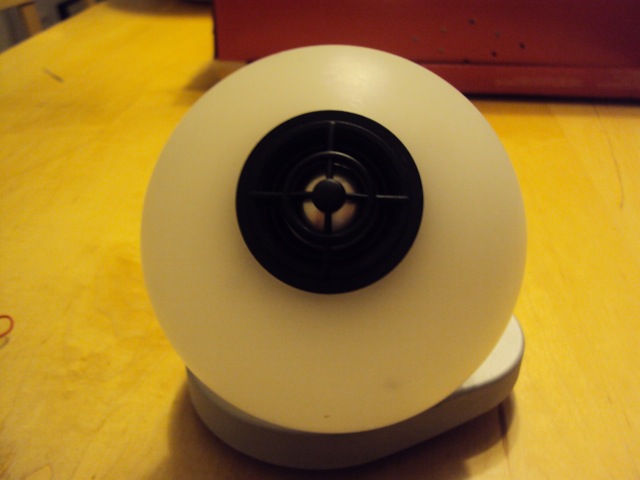
As i have shown in a picture i plan to place the tweeter as is on a nylon ball that contains the midrange. The midrange in the nylon ball will maybe angled so that we hear that driver from slightly off axis. It also will allow matching of arrivel time with the tweeter.
I plan to use as little damping on the outside of the box as posible. Maybe a blanket under the tweeter will do. The reason i do not like damping the outside much is the loss of energy we will get and also it is hard to find a damping material that is linear over frequency so we may get some iregularities off axis even if the response on axis looks fine.
I have to check if the midrange gives up before the woofer. Frequencies at that point are more then a meter long so i think i can build the woofer box rather conventionally.
As i have shown in a picture i plan to place the tweeter as is on a nylon ball that contains the midrange. The midrange in the nylon ball will maybe angled so that we hear that driver from slightly off axis. It also will allow matching of arrivel time with the tweeter.
I plan to use as little damping on the outside of the box as posible. Maybe a blanket under the tweeter will do. The reason i do not like damping the outside much is the loss of energy we will get and also it is hard to find a damping material that is linear over frequency so we may get some iregularities off axis even if the response on axis looks fine.
Hi,
Around diffraction (one round):
Horisontal wall models tweeter front plate in free air. Vertical wall separates direct wave from the around wave (for them to be visual for the eye).
To see multiple around diffractions one needs impulse source (not steady state) that allows them to be separated in time domain.
Picture generated with www.falstad.com
- Elias
Around diffraction (one round):
An externally hosted image should be here but it was not working when we last tested it.
Horisontal wall models tweeter front plate in free air. Vertical wall separates direct wave from the around wave (for them to be visual for the eye).
To see multiple around diffractions one needs impulse source (not steady state) that allows them to be separated in time domain.
Picture generated with www.falstad.com
- Elias
Hello,
More meal for thought.
A crude model for a 'water drop' shaped tweeter for around diffraction. Red arrow is direct sound, yellow arrow is path for around diffraction. Again the vertical wall separates the direct and around diffracted waves for visualisation purposes.
Wave travels around with no difficulty. Zero diffraction loudspeaker is very hard
- Elias
More meal for thought.
A crude model for a 'water drop' shaped tweeter for around diffraction. Red arrow is direct sound, yellow arrow is path for around diffraction. Again the vertical wall separates the direct and around diffracted waves for visualisation purposes.
An externally hosted image should be here but it was not working when we last tested it.
Wave travels around with no difficulty. Zero diffraction loudspeaker is very hard
- Elias
At higher freq diffraction is less:
I really wish a dB scale for these applications. Linear scale not very useful.
An externally hosted image should be here but it was not working when we last tested it.
I really wish a dB scale for these applications. Linear scale not very useful.
I will build the midrange in a Nylon sphere.
A ball diffractor:
An externally hosted image should be here but it was not working when we last tested it.
- Elias
- Status
- This old topic is closed. If you want to reopen this topic, contact a moderator using the "Report Post" button.