That sure was a great theory class by 'Prof' Scott, and it served to clarify things even for those like me who are total strangers to the rigours of an engineering classroom! But I admit it took a few reads for my brain to cool down and come out of the knots of theory ...
It is apparent that the component replacements beginning with the LTP pair and up to Q614/Q616 and the associated parts have cured a lot of problems. After adjusting VR602, the voltages are symmetrical there (though a bit low as the rails too are low on account of the series bulb protection).
Without a speaker/load, the amp starts up, the output goes to a max of nearly -6V and settles to 'zero' within about 2 seconds plus. Then the voltages at the two ends of R660 and R662 too are symmetrical.
But what happens when the speaker/load is connected (while the amp is on, with offset at zero), then both the negative voltages (Q622/Q626 end) fall to about half the positive value. But the output offset stays at very near zero without change.
Both Q620 and Q622 measure okay on a transistor/FET tester, though with widely differing Betas. But I don't have ready replacements to try, as their voltage ratings are pretty high; I am getting a substitute pair in a couple of days.
Q624/Q626 as well as the output pair (one pair only wired up) are new devices.
Hope this should lead you to smoking out the "guilty party".
Awaiting your guidance there.
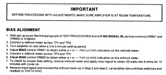
I am still confused about the bias setting pot. It is supposed to set the class AB operating point, and as such should not affect the output offset. But here Adcom advises setting the bias so that it produces about 7mV across the output device emitter resistor. (I have attached the excerpt from the service manual.) But when that control affects the symmetry of the voltages at the collectors of Q614 and Q616, what does one aim for as the best option--symmetry of the +/- voltages, or the recommended bias current indicated by the 7mV level ??
It is apparent that the component replacements beginning with the LTP pair and up to Q614/Q616 and the associated parts have cured a lot of problems. After adjusting VR602, the voltages are symmetrical there (though a bit low as the rails too are low on account of the series bulb protection).
Without a speaker/load, the amp starts up, the output goes to a max of nearly -6V and settles to 'zero' within about 2 seconds plus. Then the voltages at the two ends of R660 and R662 too are symmetrical.
But what happens when the speaker/load is connected (while the amp is on, with offset at zero), then both the negative voltages (Q622/Q626 end) fall to about half the positive value. But the output offset stays at very near zero without change.
Both Q620 and Q622 measure okay on a transistor/FET tester, though with widely differing Betas. But I don't have ready replacements to try, as their voltage ratings are pretty high; I am getting a substitute pair in a couple of days.
Q624/Q626 as well as the output pair (one pair only wired up) are new devices.
Hope this should lead you to smoking out the "guilty party".
Awaiting your guidance there.
I am still confused about the bias setting pot. It is supposed to set the class AB operating point, and as such should not affect the output offset. But here Adcom advises setting the bias so that it produces about 7mV across the output device emitter resistor. (I have attached the excerpt from the service manual.) But when that control affects the symmetry of the voltages at the collectors of Q614 and Q616, what does one aim for as the best option--symmetry of the +/- voltages, or the recommended bias current indicated by the 7mV level ??
Attachments
I am not sure I understand this:
"But what happens when the speaker/load is connected (while the amp is on, with offset at zero), then both the negative voltages (Q622/Q626 end) fall to about half the positive value. But the output offset stays at very near zero without change."
Which negative voltages are you describing here?
You say the output offset stays near zero with the load connected. But your PM said that the output went to -6 V and stayed there.
If Q620 and Q622 have very different betas, then this could be the issue. It may be that to get zero offset with no load, you have to adjust the bias all the way one way, and then when a load is connected that imbalance shows up at the load.
This is similar to theory that one of the transistors has an open collector emitter junction, but just not quite as extreme.
Here is a simplified diagram of the output circuit. with the nominal currents and voltages noted. I would be interested to see what you are measuring both with the load connected and without.
Specifically:
- With no load, and the circuit balanced, what are the voltages across the 0.22 ohm emitter resistors on both sides? This will tell us what the quiescent current is*.
- With no load, and the circuit balanced, what are the voltages at the collectors of Q614 and Q616?
This will tell us if you are compensating for some other offset source using VR602.
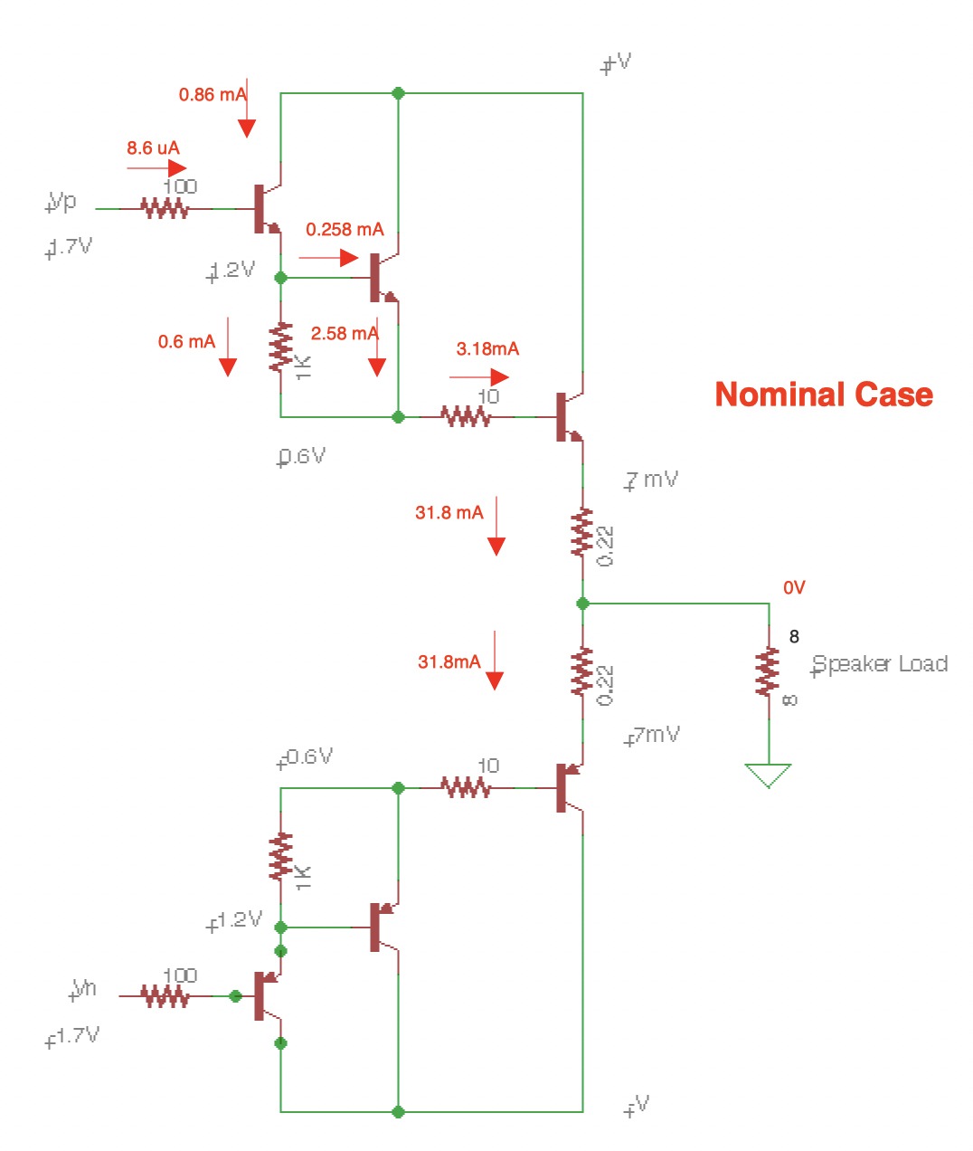
As noted in the diagram, the voltage drop on the emitter resistors should be about 7 mV, implying about 32 mA of current flow. If these are significantly different then this would probably be due to some imbalance in the overall currents flowing on either side.
I am not sure how the bias control is supposed to adjust the overall quiescent current. It clearly is designed to control the offset.
You might find some insights by using a larger load resistor. 8 ohms is so low that it requires heavy currents to drop any significant voltage across it, a nd that may be causing other issues. If you've, say, a 10 watt 100 ohm resistor, then placing that across the speaker terminals shoudl upset the balance, but not as wildly as the 8 ohm load.
* In your PM you noted that the offset with the load connected was -6 volts. If this is in fact the case, then that means the negative side output is sinking 750 mA, instead of 32. That would comprise a voltage drop of 165 mV as opposed to 7 across those emitter resistors.
One possibility is that to compensate for a shorted transistor in the negative side, you are dialing back the bias on the positive side (so with no load, the positive side is current limiting the negative side). When a load is then attached, there is no current limiting, and the negative side draws that full current pulling doen the output voltage.
"But what happens when the speaker/load is connected (while the amp is on, with offset at zero), then both the negative voltages (Q622/Q626 end) fall to about half the positive value. But the output offset stays at very near zero without change."
Which negative voltages are you describing here?
You say the output offset stays near zero with the load connected. But your PM said that the output went to -6 V and stayed there.
If Q620 and Q622 have very different betas, then this could be the issue. It may be that to get zero offset with no load, you have to adjust the bias all the way one way, and then when a load is connected that imbalance shows up at the load.
This is similar to theory that one of the transistors has an open collector emitter junction, but just not quite as extreme.
Here is a simplified diagram of the output circuit. with the nominal currents and voltages noted. I would be interested to see what you are measuring both with the load connected and without.
Specifically:
- With no load, and the circuit balanced, what are the voltages across the 0.22 ohm emitter resistors on both sides? This will tell us what the quiescent current is*.
- With no load, and the circuit balanced, what are the voltages at the collectors of Q614 and Q616?
This will tell us if you are compensating for some other offset source using VR602.
As noted in the diagram, the voltage drop on the emitter resistors should be about 7 mV, implying about 32 mA of current flow. If these are significantly different then this would probably be due to some imbalance in the overall currents flowing on either side.
I am not sure how the bias control is supposed to adjust the overall quiescent current. It clearly is designed to control the offset.
You might find some insights by using a larger load resistor. 8 ohms is so low that it requires heavy currents to drop any significant voltage across it, a nd that may be causing other issues. If you've, say, a 10 watt 100 ohm resistor, then placing that across the speaker terminals shoudl upset the balance, but not as wildly as the 8 ohm load.
* In your PM you noted that the offset with the load connected was -6 volts. If this is in fact the case, then that means the negative side output is sinking 750 mA, instead of 32. That would comprise a voltage drop of 165 mV as opposed to 7 across those emitter resistors.
One possibility is that to compensate for a shorted transistor in the negative side, you are dialing back the bias on the positive side (so with no load, the positive side is current limiting the negative side). When a load is then attached, there is no current limiting, and the negative side draws that full current pulling doen the output voltage.
I shall clarify:
If the amp switch-on is with the speaker/load already connected, then the output goes and sticks at a low of nearly -6V. Disconnect and reconnect the load, and the output is restored to zero volts.
What happens when the load is connected (after switch on without load, and now with the output offset at zero) is that the symmetrical voltages at the end of R660 and R662 vary: the -V at the Q622/Q626 end falls to about half the previous symmetrical value. I hope it is clear to you now.
I think I will put Q620/622 on the tester and give them a blast of hot air and see how they behave. Anyway I hope to get a substitute pair (probably A1370/C3476) today or tomorrow so that I could test by substitution.
I had noticed that the original Sanken output devices too had widely differing betas. So did the replacement pairs I have obtained, and am using now. I plan to try and replace them with a pair of OnSemi NJW0281G/0302G, which have exceptional SOA and better NPN/PNP Gain Matching within 10% from 50 mA to 3 A, according to the datasheet, which ought to give us better results here, IMHO. Your advice is important here too.
I shall of course try measurements with higher load resistance and report.
One thing has to be said: the erratic previous behaviour of the L-channel module has improved much and now we are getting some consistent results, leading me to believe that we are "nearly there" as regards the last gremlin or two. I hope to post more systematic voltage readings as per your suggestion. Kindly put up with the incompetence of a harassed lay person scared by the depths he is trying to plumb, though an expert is hand-holding!
I am amused that the Adcom designer's labelling of the bias pot has flummoxed you also. Perhaps we shall explore that angle once the basic issues are solved. As I had stated at the outset, my wish is to disable the DC servo, set the offset manually and then enable the servo as a "belt and braces" ploy. Once the amp behaves well (the present settling time of 2-3 seconds points to the servo correcting the output offset...?), we could perhaps take up exploring the manual setting of the offset. Then we would also need to find a way to set the quiescent bias too. Kindly keep that at the back of your mind, sir.
Warm regards
"If the amp switch-on is with the speaker/load already connected, then the output goes and sticks at a low of nearly -6V. Disconnect and reconnect the load, and the output is restored to zero volts.
What happens when the load is connected (after switch on without load, and now with the output offset at zero) is that the symmetrical voltages at the end of R660 and R662 vary: the -V at the Q622/Q626 end falls to about half the previous symmetrical value. I hope it is clear to you now."
OK, this is interesting. Seems to point to a functional but failing transistor. I suspect, as before, that Q622 id flaky. Are you doing this with or without the servo? If it is with the servo, try it with the op amp out.
The inconsistent behavior is odd, but it is a complex circuit. I suspect that with the load connected the current is high enough to drive the transistor into some odd mode. If it gets started at low current, then it is OK, or we are seeing the confounding effect of the servo.
I'll be interested to see your test results on the transistors and their replacements.
Last edited:
Ran off the end of the edit period. here is a re-post of the above, with additional thoughts.
"If the amp switch-on is with the speaker/load already connected, then the output goes and sticks at a low of nearly -6V. Disconnect and reconnect the load, and the output is restored to zero volts.
What happens when the load is connected (after switch on without load, and now with the output offset at zero) is that the symmetrical voltages at the end of R660 and R662 vary: the -V at the Q622/Q626 end falls to about half the previous symmetrical value. I hope it is clear to you now.
Once the amp behaves well (the present settling time of 2-3 seconds points to the servo correcting the output offset...?)"
OK, this is interesting. Not sure why it is unable to deal with the load at startup, but we'll figure it out. My guess is that one of the transistors is bad enough that the offset is so high that the servo can't cope with it. Once things settle down, it can.
It also tells me that the offset is load related (which is consistent with my Darlington fault theory).
First thing to do is do the voltage tests with and without a load with the servo disconnected. I think the servo is injecting all sorts of odd behavior into the circuit. The zero output with a speaker connected, disconnected and then re-connected, and subsequent steady state offset at R660 means the servo is creating that offset to compensate for an offset further down the chain.
With the servo out, and no load, adjust VR602 for zero offset at the collectors of Q614 and Q616. Then check the voltages to ground on both sides of R660 and R662. If these are not symmetrical, then you have an issue with one of the Darlington input devices (Q620/622 or Q624/626). If the output stays balanced with no load, then connect your volt meter to one side of R660, and momentarily connect a load to the speaker terminal, and record the voltage on that side of R660. Repeat with the other side of R660. If these voltages are well behaved, then do the same with R662 (this is where it helps to have a high wattage load resistor, so you can sustain an offset for some time).
There are four possibilities:
If the collector of Q624 is open, then the current to the base of Q628 will be too low, and the negative side will dominate the output.
If the collector-emitter of Q622 is shorted (possibly with some fixed resistance) then the base current of Q626 will be too high, and the negative side will dominate (this is my suspicion, because you need a lot of current to drop 6 volts across 8 ohms).
Same case with Q628 and Q626.
I also wonder about your lamps, or whatever you had in the rails. If you put a load in the rail circuit, then that will mask the effect of a shorted transistor. For example, if Q626 was shorted, but there was a series load in the rail, that would limit the current flowing through the transistor, and keep things from going truly bonkers. But it will also mask that fault. So I suggest you remove any rail loads.
Which device had a very low beta?
Apologies for the late post; but in the meantime I got a few pairs of A1370/C3467, with close enough betas, and a few pairs of OnSemi NJW281/302 output pairs, which again, have close betas, unlike the original Sanken device pairs A1492/C3856.
All the old output transistor PNPs had an average beta of about 120, while the NPNs were down at about 35. Similar values too for the NOS Sanken devices I obtained for replacement. Hence I thought I would move to OnSemi NJW devices, which are far better I gather.
A clarification about my 'protection'--I use a series bulb rated at 240V/60Watts in series with the primary the transformer as I have no variac, which I had found was better than having series resistors in the DC rails. Takes care of shorts/excess current etc and gives you enough time to take measurements.
Soldered up with one pair of output devices for testing. Replaced VR602 with a 2k Bourns trimpot. Both rails at 49.5V (with protection in series to the primary of the transformer, no Rs in the DC rails).
Switch on without speaker/load...no 'hunting' of output, as far as visible on the DMM (an analogue multimeter would have been more indicative, IMO). Adjusted VR602 for symmetrical voltages at collectors of Q614 and Q616 (1.56V). No overheating etc, all seems fine. Switch off, connect load of 47 Ohms high wattage R, switch on... very small swing of output which stabilizes in a second or so. Far better performance than earlier with old devices.
Now, switch off, disconnect load; check symmetrical voltages again, and with DMM at positive end (collector of Q614, top of diagram), connect load --> + voltage rises to near 1.6V. Repeat with DMM at negative end (bottom of diagram) --> the negative voltage falls to about -1.4V when load is connected. This, I think, should aid your diagnostics.
But for this small discrepancy, everything seems (and sounds!) fine.
Removing the DC servo IC scared me with voltages going haywire, particularly the symmetrical voltages, both going to some negative values, and I switched off without further ado. That part of testing has to wait a bit while we (you, Sir!) sort out the discrepancy in the symmetrical voltages with/without load.
The quiescent current measured across the output device emitter R is very low (just 1 mV or so) with one pair of output transistors, and with and without load connected, and with VR602 adjusted for symmetry of the +/- voltages.
Everything now seems/looks okay, but there is still some issue. What exactly it is only more testing as per your advice will reveal. I guess for the moment I shall give my poor brain a rest and try to use the amp with a speaker protection circuit, so that regular use might stress some components and hopefully throw up the villain of the piece.
I await your guidance.
When you say "output transistors, is that everything after Q614/616?Apologies for the late post; but in the meantime I got a few pairs of A1370/C3467, with close enough betas, and a few pairs of OnSemi NJW281/302 output pairs, which again, have close betas, unlike the original Sanken device pairs A1492/C3856.
All the old output transistor PNPs had an average beta of about 120, while the NPNs were down at about 35. Similar values too for the NOS Sanken devices I obtained for replacement. Hence I thought I would move to OnSemi NJW devices, which are far better I gather.
A clarification about my 'protection'--I use a series bulb rated at 240V/60Watts in series with the primary the transformer as I have no variac, which I had found was better than having series resistors in the DC rails. Takes care of shorts/excess current etc and gives you enough time to take measurements.
Soldered up with one pair of output devices for testing. Replaced VR602 with a 2k Bourns trimpot. Both rails at 49.5V (with protection in series to the primary of the transformer, no Rs in the DC rails).
Switch on without speaker/load...no 'hunting' of output, as far as visible on the DMM (an analogue multimeter would have been more indicative, IMO). Adjusted VR602 for symmetrical voltages at collectors of Q614 and Q616 (1.56V). No overheating etc, all seems fine. Switch off, connect load of 47 Ohms high wattage R, switch on... very small swing of output which stabilizes in a second or so. Far better performance than earlier with old devices.
Now, switch off, disconnect load; check symmetrical voltages again, and with DMM at positive end (collector of Q614, top of diagram), connect load --> + voltage rises to near 1.6V. Repeat with DMM at negative end (bottom of diagram) --> the negative voltage falls to about -1.4V when load is connected. This, I think, should aid your diagnostics.
But for this small discrepancy, everything seems (and sounds!) fine.
Removing the DC servo IC scared me with voltages going haywire, particularly the symmetrical voltages, both going to some negative values, and I switched off without further ado. That part of testing has to wait a bit while we (you, Sir!) sort out the discrepancy in the symmetrical voltages with/without load.
The quiescent current measured across the output device emitter R is very low (just 1 mV or so) with one pair of output transistors, and with and without load connected, and with VR602 adjusted for symmetry of the +/- voltages.
Everything now seems/looks okay, but there is still some issue. What exactly it is only more testing as per your advice will reveal. I guess for the moment I shall give my poor brain a rest and try to use the amp with a speaker protection circuit, so that regular use might stress some components and hopefully throw up the villain of the piece.
I await your guidance.
The very low NPN betas were probably your problem. That would unbalance the output and cause it to go negative.
I am guessing that if you let the amp sit for a while with no load, those collector voltages will settle back to being symmetrical. There is no reason if they were set equal before the load was applied, that the balance would change permanently with no change in VR602. I think what you are seeing is that the servo has corrected some offset, and it has a very long time constant.
You might try removing the bulbs in the rails, since the amp is not smoking anything. It is possible that they are not matched, so when a load is applied, one rail falls more than the other, and the servo is compensating for that.
Also, just because it is probably now safe to do so, attach an 8 ohm load, and adjust VR602 for balance WITH the load applied. It is possible that there is some inherent imbalance in the circuit, and setting the balance with a load is different than without a load. Since it is designed to work WITH a load, and it seems to be behaving more or less properly, set it up with a real load and see what it does. I would not be surprised to see, if it was working into a load and was balanced using Vr602, that removing the servo had little effect.
I had clarified about my 'protection'--I use a series bulb rated at 240V/60Watts in series with the primary of the transformer...no Rs in the rails.You might try removing the bulbs in the rails, since the amp is not smoking anything. It is possible that they are not matched...
Yes, by output transistors, I mean the last power devices (3 + 3) in the triple Darlington set.
Shall try what you have suggested as soon as I return and report back.
Thanks and regards
My thought about the bulbs is this: They are acting as a form of current dependent resistance (that's why the offer some protection). If, as you say, the rails are drooping as a result of the bulbs, then there is also a distinct possibility that an imbalance in the bulb resistances would also cause an imbalance in the output voltage under load. So it is possible that with no load you can balance the circuit, but when a load is applied the bulbs cause the offset, because under load more current is flowing through the rails. Of course if, as I suggested, you balance the amp under a load, then it should be OK. But, if the amp is not trying to self destruct, then the bulbs are only adding distortion, and uncertainty in the bias.
As we discussed earlier, you should also either replace or test Q620, Q624, Q618 and Q622.
As we discussed earlier, you should also either replace or test Q620, Q624, Q618 and Q622.
It looks like everything changed on diyaudio while I was away! Ah, change is the only constant thing...
Yes, I did put in new devices from Q612 onwards, including a pair of NJW281/302 power devices as outputs for testing. The amp powered up normally (with the protection bulb--only one in series with the transformer primary) and everything was quite close to normal. But again some gremlin was there. I tried my 'hot air blast' trick with a focussed jet, which brought out the flakiness of Q610--on two earlier occasions it had tested and measured well. You learn not to trust out-of-circuit tests! Replaced it, and things were stable after that.
Now it is going to be wiring in all the three pairs of output devices, putting in a DC protection relay circuit module, and using the amp for some time as part of extended testing. It has been one great roller-coaster ride for me, but I enjoyed it thanks chiefly to the patient hand-holding of Cogeniac.
Now that things have come to a satisfactory conclusion, let me open a dedicated thread and post all the 545-related stuff there.
Thanks and warm regards to all!
It's been pleasure Prof. Good luck!It looks like everything changed on diyaudio while I was away! Ah, change is the only constant thing...
Yes, I did put in new devices from Q612 onwards, including a pair of NJW281/302 power devices as outputs for testing. The amp powered up normally (with the protection bulb--only one in series with the transformer primary) and everything was quite close to normal. But again some gremlin was there. I tried my 'hot air blast' trick with a focussed jet, which brought out the flakiness of Q610--on two earlier occasions it had tested and measured well. You learn not to trust out-of-circuit tests! Replaced it, and things were stable after that.
Now it is going to be wiring in all the three pairs of output devices, putting in a DC protection relay circuit module, and using the amp for some time as part of extended testing. It has been one great roller-coaster ride for me, but I enjoyed it thanks chiefly to the patient hand-holding of Cogeniac.
Now that things have come to a satisfactory conclusion, let me open a dedicated thread and post all the 545-related stuff there.
Thanks and warm regards to all!
@ Anatech
Let me place a request before you as Admin.
I had requested for some help regarding Adcom GFA-545-II on Page 20, Post # 395 of this thread.
The ensuing discussion had helped me to resolve the issue.
Still I perceive that the 545-related posts do 'pollute' this thread. So I have re-posted the entire related material, (in an orderly, but slightly edited fashion to maintain continuity) in a new thread at:
https://www.diyaudio.com/community/threads/yet-another-adcom-gfa-545-ii-restored.381567/
I hope this could be of help to others wishing to delve into the issues plaguing the Adcom GFA-545-II.
This being the case, I trust you would devote some time to delete all the 545-related posts from this thread, except perhaps this one.
Thanks and warm regards.
GFA-565 parts shortages: 
Parts shortages are stressing me out! And threatening my business. I'm worried that the Central Semiconductor CMXSTB400 is about to go extinct. Mouser is the only supplier, with 371 in stock and none on order.
The only other stabistor that I'm aware of, is the Nexperia BAS17, a single stabistor diode in SOT23.

So I've added SOT23 footprints to the bottoms of my BFA-565 boards, so the boards can accept all three kinds; the original through-hole stabistors, the CMXSTB400 or the BAS17. It works out pretty well, and some people may find these SOT23 packages easier to solder than the SOT26.

Top-side accepts original through-hole stabistors, or SOT26 CMXSTB400.

Also LT1012's and OP97's in DIP-8 are currently nowhere to be found, and I'm running out of stock.
So I've added dual DIP-8/SO08 footprints.

I'm also starting to have trouble finding film and electrolytic capacitors, transistors... Even these little JST board connectors are getting hard to find! I had to order quantity 2000 from Utmel in China.

These JST connectors are far from obsolete; they're used in everything!
Anyways, that's all, I don't have an actual question, but that's what's up with GFA-565 boards these days.
Parts shortages are stressing me out! And threatening my business.
I'm worried that the Central Semiconductor CMXSTB400 is about to go extinct. Mouser is the only supplier, with 371 in stock and none on order.The only other stabistor that I'm aware of, is the Nexperia BAS17, a single stabistor diode in SOT23.
So I've added SOT23 footprints to the bottoms of my BFA-565 boards, so the boards can accept all three kinds; the original through-hole stabistors, the CMXSTB400 or the BAS17. It works out pretty well, and some people may find these SOT23 packages easier to solder than the SOT26.
Top-side accepts original through-hole stabistors, or SOT26 CMXSTB400.
Also LT1012's and OP97's in DIP-8 are currently nowhere to be found, and I'm running out of stock.
So I've added dual DIP-8/SO08 footprints.
I'm also starting to have trouble finding film and electrolytic capacitors, transistors... Even these little JST board connectors are getting hard to find! I had to order quantity 2000 from Utmel in China.
These JST connectors are far from obsolete; they're used in everything!
Anyways, that's all, I don't have an actual question, but that's what's up with GFA-565 boards these days.
Good to know. I see the CMXSTB200 can only be ordered int lots of 3K units!! That's a lot of amplifiers!!GFA-565 parts shortages:
Parts shortages are stressing me out! And threatening my business.
The only other stabistor that I'm aware of, is the Nexperia BAS17, a single stabistor diode in SOT23.
View attachment 1028521
So I've added SOT23 footprints to the bottoms of my BFA-565 boards, so the boards can accept all three kinds; the original through-hole stabistors, the CMXSTB400 or the BAS17. It works out pretty well, and some people may find these SOT23 packages easier to solder than the SOT26.
View attachment 1028523
Top-side accepts original through-hole stabistors, or SOT26 CMXSTB400.
View attachment 1028526
Also LT1012's and OP97's in DIP-8 are currently nowhere to be found, and I'm running out of stock.
So I've added dual DIP-8/SO08 footprints.
View attachment 1028525
I'm also starting to have trouble finding film and electrolytic capacitors, transistors... Even these little JST board connectors are getting hard to find! I had to order quantity 2000 from Utmel in China.
View attachment 1028530
These JST connectors are far from obsolete; they're used in everything!
Anyways, that's all, I don't have an actual question, but that's what's up with GFA-565 boards these days.
Good to hear!!
@ Cogeniac
My Adcom 545 has been going strong all these weeks... one more "Thank you" to you and the others who helped with the detailed troubleshooting info.
Many thanks to the people on this thread for help with restoring these beautiful sounding GFA-565s. I rebuilt the input boards with the Hoppe's Brain boards and really happy with the results. Also replaced the caps on the output modules, 20w resistor and caps on relay board. Driving with a GFP-565, this setup really shows how much I need to upgrade my Martin Logan Mosaic speakers. I planned to rebuild and sell with the pre-amp but I've really fallen in love with this Adcom gear.

- Home
- Amplifiers
- Solid State
- Yet Another Adcom GFA-565 Thread