Decided to sell these. They really do deserve an upgrade of the speakers and wife shutdown any discussion on buying Apogees or Magnepan 3.x/20.1, which they would be awesome with!Many thanks to the people on this thread for help with restoring these beautiful sounding GFA-565s. I rebuilt the input boards with the Hoppe's Brain boards and really happy with the results. Also replaced the caps on the output modules, 20w resistor and caps on relay board. Driving with a GFP-565, this setup really shows how much I need to upgrade my Martin Logan Mosaic speakers. I planned to rebuild and sell with the pre-amp but I've really fallen in love with this Adcom gear.
View attachment 1037698
You know those big planars have a very poor WAF, Wife Acceptance Factor😊That could be grounds for divorce.")
Hey y'all, here's my crappy LT Spice model of the GFA-565. I've just used default generic transistor types included in LT Spice, so AC analysis will not be accurate. However, it is useful for investigating how the circuit actually works.
Feel free to make improvements and share! Especially, the correct transistor models need to be added.
Feel free to make improvements and share! Especially, the correct transistor models need to be added.
Attachments
Troubleshooters may find my new, annotated schematic for the GFA-565 helpful. There are troubleshooting tips, voltage and current readings, etc... This is all based on customer feedback, and the issues I see people struggle with. Also I've made the schematic much more readable, by re-arranging components in a more logical order.
I'm working on an improved version of my BFA-565 boards, to be called the EBFA-565, 😸 and making the schematic more useful is part of the project.
I'm working on an improved version of my BFA-565 boards, to be called the EBFA-565, 😸 and making the schematic more useful is part of the project.
Attachments
Darn. I just realized you are in Madison. My son lives in Chicago, and in July we visited and took him and his wife to Spring Green to see Taliesin, and to watch a showing of Hamlet that the American Player's Theatre. I should have liked you up and dropped in to say hi. Beautiful area!!Troubleshooters may find my new, annotated schematic for the GFA-565 helpful. There are troubleshooting tips, voltage and current readings, etc... This is all based on customer feedback, and the issues I see people struggle with. Also I've made the schematic much more readable, by re-arranging components in a more logical order.
I'm working on an improved version of my BFA-565 boards, to be called the EBFA-565, 😸 and making the schematic more useful is part of the project.
Well, after several years of interruption (COVID, a house remodel, and a just a lot of work!!) I managed to find some time to dust off my work bench and try out my GFA 565 board. When last I posted, I had completed a revised board and was getting ready to try it out. I had to clear off 18 months of junk from my bench, and re-remember how to set up the board with the amplifier supplies and such. I used a Varian this time, and there was no drama. However, the board did not work. Try as I might, I could not get any signal through it, and the output was pinned negative.
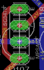
After some head scratching, and testing all of the various currents and such, I concluded that, for some reason Q111 and Q110 were bad. As I was pondering Q110, something seemed off about how it was installed. On this board spin, I had used Anatech's ambidexterous ECBE layout, so I could use some of the alternate replacements that come with a different pinout. In doing this I had also labeled the pins, just in case there was any uncertainty. This setup works great for the MSP/KSP substitutions (which are CBE, where their older counterparts are ECB). Here's the layout for that.

However, looking at Q110, it seemed that the pinouts were wrong. After quite a bit of back and forth with the data sheets, I discovered that the BC550/BC560 replacements for the SC1815 and SA1015 devices use yet a different pinout. Essentially, the sequence is the same (ECB), but the direction relative to the case is flipped. I had simply replicated the layout above, but in fact what I should have done for this specific devices was this layout:

I was using an SC1815 device, so following the incorrect layout, the transistor was installed with the base and collector flipped.
I changed this out, and replaced Q111 (I think Q111 blew while I was tinkering around trying to get things to balance. I had a small smoke event when R127 overheated. I had noticed that the Q111 heat sink was very hot, so it is possible it was just bad to start with).
As soon as I did this, voila! Working amplifier.
So I need to do a very minor re-spin on the board, and can build up new boards for all of my amplifiers (I have 7 of these - bought back in the old days when they were "unrepairable...before we collectively figured out how to breathe life back into these lovely amps, and hence cheap!!
Here is a pic of the input at 1 volt and the output at 50 volts per division (this is open loop, and no servo).

And here is the new board in its test jig. The sharp eye will notice that I am using the CMX surface mount stabistors (I bought a bunch before they went EOL) in place of the KB devices. .

Cheers.
Scott
After some head scratching, and testing all of the various currents and such, I concluded that, for some reason Q111 and Q110 were bad. As I was pondering Q110, something seemed off about how it was installed. On this board spin, I had used Anatech's ambidexterous ECBE layout, so I could use some of the alternate replacements that come with a different pinout. In doing this I had also labeled the pins, just in case there was any uncertainty. This setup works great for the MSP/KSP substitutions (which are CBE, where their older counterparts are ECB). Here's the layout for that.
However, looking at Q110, it seemed that the pinouts were wrong. After quite a bit of back and forth with the data sheets, I discovered that the BC550/BC560 replacements for the SC1815 and SA1015 devices use yet a different pinout. Essentially, the sequence is the same (ECB), but the direction relative to the case is flipped. I had simply replicated the layout above, but in fact what I should have done for this specific devices was this layout:
I was using an SC1815 device, so following the incorrect layout, the transistor was installed with the base and collector flipped.
I changed this out, and replaced Q111 (I think Q111 blew while I was tinkering around trying to get things to balance. I had a small smoke event when R127 overheated. I had noticed that the Q111 heat sink was very hot, so it is possible it was just bad to start with).
As soon as I did this, voila! Working amplifier.
So I need to do a very minor re-spin on the board, and can build up new boards for all of my amplifiers (I have 7 of these - bought back in the old days when they were "unrepairable...before we collectively figured out how to breathe life back into these lovely amps, and hence cheap!!
Here is a pic of the input at 1 volt and the output at 50 volts per division (this is open loop, and no servo).
And here is the new board in its test jig. The sharp eye will notice that I am using the CMX surface mount stabistors (I bought a bunch before they went EOL) in place of the KB devices. .
Cheers.
Scott
Attachments
Last edited:
Hi Scott,
Yes, some pro-electron parts (European) are reversed or swap C-B pins. That's why I laid out the tester this way. You can deal with everything. As always with a substitute, you must check the device datasheet to make sure. Since I'm old, I then test to make absolutely certain. It takes far to long to troubleshoot instead of just checking.
I like the spacing on your board too.
Now, what would be cool is allow the diff pair to be balanced naturally. Give the DC servo a bipolar supply and try it without the servo, cap to common for the feedback resistor. You want the diff pair balanced, servo or no. That will eliminate the DC offset that settles at startup. If you don't need the servo - FANTASTIC! Just don't stuff it. If you do, short the cap position and use the servo. This will make the Adcom amps able to use a protection relay, or just simply make them a much better amplifier.
-Chris
HI Chris;
Not quite sure I follow you on the servo business.
As I understand it, the servo is really there to fine tune any offset that may occur over time and/or temp. I have not measured the overall offset, but it appears to be very low without the servo. Part of this is that I used some multi turn Vishay trimmers in series with R144/145 so I was able to dial in the bias currents on the diff pairs to within a micro amp or so (drop across R106/107 was equal to within 1 mV. It was impressive to watch the amp suddenly calm down once I got this tweaked in. As I noted in other earlier posts, the offset is almost entirely a result of mismatch between the positive and negative diff pairs.
What I don't quite follow is "Give the DC servo a bipolar supply and try it without the servo, cap to common for the feedback resistor." Do you mean the op amp feedback resistor, or one of the actual amplifier feedback resistors? Currently R116 is lifted, so there is no offset input to the diff pairs.
I have also considered trying to make an inherently balanced current source. The current design is really two semi independent sources. Seems like an interesting solution would be integrate them, so that the currents are always equal.
The idea I started with was to actually have a bipolar current source, so that the current pulled through the positive diff pair just continues down to drive the negative diff pair. That ways they are always the same because there is only one current path. Here is a conceptual circuit. Not really sure if the ground section is necessary. If the circuit is actually balanced, then that ground should be virtual.

Scott
Not quite sure I follow you on the servo business.
As I understand it, the servo is really there to fine tune any offset that may occur over time and/or temp. I have not measured the overall offset, but it appears to be very low without the servo. Part of this is that I used some multi turn Vishay trimmers in series with R144/145 so I was able to dial in the bias currents on the diff pairs to within a micro amp or so (drop across R106/107 was equal to within 1 mV. It was impressive to watch the amp suddenly calm down once I got this tweaked in. As I noted in other earlier posts, the offset is almost entirely a result of mismatch between the positive and negative diff pairs.
What I don't quite follow is "Give the DC servo a bipolar supply and try it without the servo, cap to common for the feedback resistor." Do you mean the op amp feedback resistor, or one of the actual amplifier feedback resistors? Currently R116 is lifted, so there is no offset input to the diff pairs.
I have also considered trying to make an inherently balanced current source. The current design is really two semi independent sources. Seems like an interesting solution would be integrate them, so that the currents are always equal.
The idea I started with was to actually have a bipolar current source, so that the current pulled through the positive diff pair just continues down to drive the negative diff pair. That ways they are always the same because there is only one current path. Here is a conceptual circuit. Not really sure if the ground section is necessary. If the circuit is actually balanced, then that ground should be virtual.
Scott
Hi Scott,
Sorry, I was thinking of the 555 MKII. They purposely unbalanced the diff pair, fed the servo from one polarity supply only (since they knew where the offset was going to be).
The 565 is naturally balanced. R119 could have a capacitor inserted between it and common. That reduces the gain at DC to 1 and you should have very good DC offset figures assuming a matched set of diff pairs. I don't care for DC servos to be honest. Get the amp right and you don't need them. A manual DC offset pot can reduce a small offset to > 1mV and it shouldn't drift very much at all.
Your idea won't work. The NPN diff pair emitters will be below ground, the PNP pair above ground potential. JC did it with J-Fets, but BJT junctions need to be forward biased. Good thought though. Consider, the transconductance of the PNP and NPN pairs aren't equal anyway. Therefore the tail currents need not be exactly equal. You could figure out the average difference and scale the tail currents for very rough compensation, but I'm not sure if that would make a big difference. There's an avenue to explore for someone.
"The NPN diff pair emitters will be below ground, the PNP pair above ground potential....Consider, the transconductance of the PNP and NPN pairs aren't equal anyway. Therefore the tail currents need not be exactly equal."
Good point. So maybe some sort of circuit that actively adjusts the two current sources based on their relative balance. That would look a bit like the servo, except that the servo would be sensing the current difference in the tails, and would be controlling the current source. That way nothing is in the signal path. To ponder this a bit, I decided to set out the current control circuit as it was originally designed. This is shown below.
The circuit is a bit hard to follow because there are three things going on at the same time. 1) the current sources; 2) the soft start control; and 3) the thermal cutoff.
Starting with the soft start, we see that when the softitart relay comes on, it illuminates the photo diode in the opto-coupler (upper right transistor. This causes that photo transistor to conduct. This turns on Q502, which in turn forward biases Q119, and reverse biases zener diode Q115.
The breakdown voltage of D115 is 2.5 volts, so this turns on Q118, allowing the current sources to start operating. What this means is that until the time delay on the soft start board expires, there is no current flowing in the main amplifier board, and this current starts to flow when enough time has passed for the big caps to charge up.
There are two thermal switches connected to the circuit. These are mounted on the big main heatsinks. For simplicity, I have shown those as a single switch connected to Q119. Normally these are closed, and this effectively shorts out the the front panel thermal protection indicator LED. If the thermal switches open, this LED is powered, and Q119 is open circuited, which de-powers the D115 zener, thereby shutting down the current sources.
So there is a fair amount of this circuit devoted to turning the current sources on and off.
Now the real sho is the actual current sources.
Once D115 is powered and in breakdown, the base emitter junction of Q118 is forward biased, and the current flow in the collector of Q118 is (2.5-0.7)/825=2.2 mA. This current is drawn through R148 and D114, causing the D114 LED to illuminate. This LED has a stable forward voltage of 2.1 volts, which then sets the current through Q115 at (2.1-0.7)/499=2.8 mA. Note that this is constant as long as the voltage fixed by the LED is constant.
When Q118 conducts, this also turns on Q117, which forward biases D113, thereby creating the same current source as Q115, but opposite polarity.
The value of these currents is thus set primarily by three things:
1) The value of the collector resistor (R144 or R154, depending on which current source you are looking at).
2) The VBE value of Q115 or Q116
3) The forward voltage of the LEDs (D114 and D113).
Because the gain of the overall control board is very high, and because it is DC coupled, any offset at the input stage will be amplified through the board, and will be reflected as an output offset. Other components in the circuit will also contribute to these offsets, but these are not necessarily amplified. The closed loop gain of the amplifier board is 20dB (a factor of about 100). The load resistors in the diff pairs are 1K ohm, so a 0.1 mA difference in diff pair current will produce a 100 mV input offset, which will become a 10 volt offset at the output!! So, clearly it is critical that the inputs be balanced.
One observation about the circuit below is that it is really two independent current sources. Each depends on its own component values, and there is no inter-relationship between them. I think that's a lost opportunity.
I'll ponder how one might interlink these so that a change in one will cause a change in the other.
Yep. I see that now. Otherwise the inputs will each float above zero. If we assume the inputs are at zero, then the emitters are at least 0.7 volts on the other side of zero, and if the current is 1.2 mA per leg, then the voltages on the collectors of the current source transistors will be another 0.4 volts down from there.Hi Scott,
The diff pair emitters need to be on the other side of ground from what you are suggesting.
Yep, plus the drops across the degeneration resistors.
I think the factory tail currents are fine. You can go crazy trying to make something perfect. Would we like CMRR? Sure! But sometimes the trouble to achieve it may be more than it's worth. That, and consider failure modes and how hard it would be to troubleshoot. How about someone building it and suffers an out of tolerance part (not far).
You have an improved circuit that works well.
Decided to test out the board with full feedback, and check the servo. I had disconnected R116 while bringing the board up, and without any feedback, the op amp input is floating. I found when I connected it, the output would clip on one side. Turned out the op amp was cooked. Replaced that, and hooked up the resistor and all is well. I see about 1.5 volts offset on each of the outputs, and by joining them with two 330 ohm resistors to simulate the output section. The offset at the common junction between them is under 1 mV.
So, I am comfortable that this board works. Ordered 8 of them, so now I can start refurbishing my stable of old 565s.
So, I am comfortable that this board works. Ordered 8 of them, so now I can start refurbishing my stable of old 565s.
- Home
- Amplifiers
- Solid State
- Yet Another Adcom GFA-565 Thread