Grant Fidelity MK2 tube buffer caps mod
Hello zcables,
I saw your post and the mod you did to your Grant Fidelity tube buffer. I also have a Grant Fidelity MK2 and thought why not mod mine. And thanks to your post and especially the photo I did just that with great results. I used Clarity SA Caps. As soon as I reconnected the buffer to my system, Sony PS1 (1001) modded using Dog Breaths mod suggestions and NAD 326BEE amp the first thing I noticed was the clarity of the sound (really, no pun intended). The buffer now has over 100 hours on the new caps and is sounding sweet.
I will repeat what you said about removing and installing the caps. No need to access the bottom of the board. Desolder the caps from the top side of the board. Cut the new cap leads just long enough to pass through to the bottom of the board.
Happy listening,
Marvin
Attachments
Last edited:
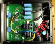
This is my mod
I can't really say how or if it sounds better, but it was only $38 bucks shipped and I feel happy just thinking about it")
Claritycaps from Madisound
Input
2x ESA 2.2uf
Output
4x SA .47uf
I used a 40w solder iron, was too big but my 15w was too small.
I watched YouTube videos to learn how to solder.
I can't really say how or if it sounds better, but it was only $38 bucks shipped and I feel happy just thinking about it
Claritycaps from Madisound
Input
2x ESA 2.2uf
Output
4x SA .47uf
I used a 40w solder iron, was too big but my 15w was too small.
I watched YouTube videos to learn how to solder.
Attachments
There seems to be a lot of negativity here from some recent posts.
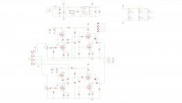
Yes - the schematic is dissapointing - especially, after looking at the Aikido and White Cathode followers.
However, tinkering with the Yaqin CD3 does provide inspiration to build a tube preamp.
Even a tube pre with a transformer coupled output.
The CD3 was $159 + $15 shipping.
So I'm not sure about the comment about fancy case and sold for a high price.
Clearly in some impedance situations, the Yaqin CD3 can provide impedance improvement.
Zin > 1 Meg
Zout ~ 180 ohms
Coupling caps are quite influential on the sonics.
Changing the coupling caps in the CD3 can be used to reduce resolution
and thus mask residual harshness from a digital source.
.
negativity?
yes, 100% negative feedback as a matter of fact....
impedance improvement?
well of course, tubes grids biased negative and not
allowed to draw current is indeed very high impedance,
in the megohms range so what is new?
input and output coupling caps are used here because the topology does not allow otherwise...
Error, and I can't edit my own post?
Should say:
Input:
2x ESA .22uf
I can't really say how or if it sounds better, but it was only $38 bucks shipped and I feel happy just thinking about it
Claritycaps from Madisound
Input
2x ESA 2.2uf
Output
4x SA .47uf
I used a 40w solder iron, was too big but my 15w was too small.
I watched YouTube videos to learn how to solder.
Should say:
Input:
2x ESA .22uf
Please note that even though film caps are "Non Polarized", the outside
of the foil should be used as a shield - which means it should be connected
to the low Z side of the circuit.
.
Hi Uunderhill
How do I tell which end is which on my Dayton film caps?
Dayton Audio DFFC-0.47 0.47uF 400V By-Pass Capacitor - Capacitors - Crossovers & Components - Loudspeaker Components
12V operation of a CD3 or similar
Sort of easy. 12Vdc to the 2 tubes heaters in series vs 6.3V x2, and then a Taylor Edge HPVS
Taylor Electronics Services HVPS
Faraday shield the top of the coil with copper foil tied to ground.
You can also "trick" that HVPS to go even higher with 12V input using a 7805 +5V shoved in one of the inputs, see attached.
Convert SD-CD3, to a 12volt external power source ?
(verses ac power.)
Wonder if it could be easily done, or not ?
Thanks
Sort of easy. 12Vdc to the 2 tubes heaters in series vs 6.3V x2, and then a Taylor Edge HPVS
Taylor Electronics Services HVPS
Faraday shield the top of the coil with copper foil tied to ground.
You can also "trick" that HVPS to go even higher with 12V input using a 7805 +5V shoved in one of the inputs, see attached.
Attachments
COnverting to CD3 12V operation
I wasn't thinking, you could also use a LM317 or 7805 to run the tube heaters in parallel at 6.3? Vdc, with a 7805 I think you can put diodes in series with the reference leg and force it to regulate at a higher output V? And LM317 you would just "program" with resistors etc. Either way, you can get full voltage to 6.3V heaters, or, "starve" them a little, or over_do it. I'd make sure you have enough current for the heaters based on data sheets.
I doubt the CD3 would sound good off un-boosted low voltage DC. The HVPS I mentioned below HAS been used in audio before, again, Faraday shield the coil on that -- Copper foil? Ground it? You can make a high voltage source with a 555 IC etc but probably not for what the HVPS I mentioned, sells for, if you factor in TIME.
Sort of easy. 12Vdc to the 2 tubes heaters in series vs 6.3V x2, and then a Taylor Edge HPVS
Taylor Electronics Services HVPS
Faraday shield the top of the coil with copper foil tied to ground.
You can also "trick" that HVPS to go even higher with 12V input using a 7805 +5V shoved in one of the inputs, see attached.
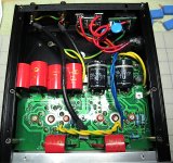
Can I have some help and advice please. I bought the 4 x .47uf clarity caps to mod my new buffer, but when I opened it, it has 2 x 4.7uf caps instead. The solder points are there for the 4 x .47 caps. My question is can I de solder the 2 big caps and just solder in the 4 x .47uf caps or do I need to, or is it better to, buy 4.7uf clarity caps to replace the 2 installed. I wasn't sure if any other alterations had been made to circuit which would have stopped me putting in the 4 smaller caps, or if there is an advantage to the 2 bigger caps. I'm in uk so on 230v, if that makes any difference. Your help and advice would be greatly appreciated
Ray
Ray
I don't know why but I have seen this a lot, in fact on every threat about the Yaqin CD3 ( I have one myself to play around with) Why is everybody replacing the 4 0.47uF caps with 4*0.47uF instead of 2*1uF of better quality ? The caps are directly in parallel on the PCB. This will save you quite some money for exactly the same result. The only reason why there are 2 * 0,47uF in parallel per channel is because they use very cheap X class caps wich do not come in sizes bigger then 0,47 uF. That's the one and only reason for this, just economics, nothing to do with quality. Well, quality for money maybe, because the x-caps are not the that terrible, they are dirt cheap because they are produced and used by the millions. So I don't think there is a better sounding cap for $0,10.
Just replace them with 1uF, saves money, saves place, saves frustration on implementation.
Just replace them with 1uF, saves money, saves place, saves frustration on implementation.
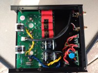
Oh and one free upgrade. Cut the yellow wire between the input and output rca's. I really don't have a clue why they put it there in the first place but it creats a little groundloop inside the unit. Just cut it and noise drops another couple of dB's. Don't be afraid to.do it, it really does not belong ther anyway, that's faulty engeneering.
Speaking about faulty engeneering, I strongly advice anyone with a Yaqin Cd3 to put some coupling cap bleeding resistors on the input and output caps, they do belong there and have a safety purpose. This thing can kill either you cd player or your amp if plugged when hot, no kidding. It does not meet safety regulations. It's a wonder it sounds decent, engeneering wise it's a piece of crap. I have wrote about this in the past, just search. In plane simple words, just solder a resistor of as high as 300kOhm to 1 Mohm across the input terminals and a 100k resistors across the output terminals and you are safe. Soundwise it does not make any difference. This is again cost cutting, like everything else on this unit.
Speaking about faulty engeneering, I strongly advice anyone with a Yaqin Cd3 to put some coupling cap bleeding resistors on the input and output caps, they do belong there and have a safety purpose. This thing can kill either you cd player or your amp if plugged when hot, no kidding. It does not meet safety regulations. It's a wonder it sounds decent, engeneering wise it's a piece of crap. I have wrote about this in the past, just search. In plane simple words, just solder a resistor of as high as 300kOhm to 1 Mohm across the input terminals and a 100k resistors across the output terminals and you are safe. Soundwise it does not make any difference. This is again cost cutting, like everything else on this unit.
When you say "just solder a resistor of as high as 300kOhm to 1 Mohm across the input terminals and a 100k resistors across the output terminals and you are safe" I'm not sure what you mean. Is that where in caps are soldered in?
Have you got a picture so that I know what you mean?
Cheers for the advice.
Have you got a picture so that I know what you mean?
Cheers for the advice.
Last edited:
- Home
- Source & Line
- Analog Line Level
- Yaqin SD-CD3 Tube Buffer - upgrading caps