Absolutely! But after formulating a theory, the next step is to postulate an experiment that can validate or invalidate the theory. And in fact, before formulating a theory, one should first validate the observations.
If you hear a difference, there are multiple explanations and theories. At the most basic level, there might be a real, physical difference, but it might also be that the perceived difference is caused by confirmation bias. Thus the first thing to do is to isolate the effect of bias. Fortunately there is a relatively easy way to do that, by using a double-blind listening test.
You're right, and that's exactly what i wanted to say: we need a number of other listeners to validate or discard the results Ninosimona reported. I think we can accept the results even if they're not blind...
")
Of course, measurements of the resulting audio signal would be necessary anyway, but it shouldn't be a problem for most of us.
So there is someone between the thread readers who's brave enough to test the mod?
Funny that's the opposite way to how the designs I work on in electronics are done... lots of boring working out the solution to the design requirement, some experimentation is part of the cycle, but it is considered experimentation with measurement's to determine the results!
Ninosimona did the "boring" work to find a solutions to a problem he (thinks to have) found. He can be right, or he can be wrong.
Now we need the experimentation and measurements work to be done... he did by himself, but a single listener experience can't be enough to be sure about the results (considering the lack of measurements). That's why someone else should try...
Ninosimona did the "boring" work to find a solutions to a problem...
There is no problem..
You're right, and that's exactly what i wanted to say: we need a number of other listeners to validate or discard the results Ninosimona reported. I think we can accept the results even if they're not blind...
Not really. The same confirmation bias could be affecting all listeners - especially if there is a strong claim that a difference exists. Groupthink (especially in a small, closed community) is a very real effect.
Under those conditions, 10 listeners all agreeing there is a difference in sighted listening is not any more evidence than a single listener.
Again, a double-blind listening test would eliminate the effects of both confirmation bias and groupthink - so why are so many of us reluctant to do a double blind test?
You're right, and that's exactly what i wanted to say: we need a number of other listeners to validate or discard the results Ninosimona reported. I think we can accept the results even if they're not blind...
Nope.
Hi,
To illustrate the normal work of the reclock it will be enough just to make simple measurement, for this purpose you will need at least 200MHz DSO and a limit test option (almost everyone DSO has this function).
If you haven’t got a DSO, maybe some basic mathematics will help:
Since you already read about the principle of working of the XMOS processor, you probably convinced yourself that the audio data are synchronously taken by external clock (has nothing in common with the XMOS PLL) in this case applied after galvanic isolation SI8661 with 350 picosec. p-p jitter. The last number have to be multiply by 2, cause MCLK is returned from the oscillator side – i.e. the absolute jitter:
XMOS jitter -> lower than 2picosec RMS (2picosec RMS ~ 30picosec p-p)
30+350+350 <800picosec p-p, so it’s much lower than 20ns. I hope that the numbers are enough to convince you that the reclock is no wrong if you haven’t convince d by measurement. Regarding reclock – it’s job is to reduce the jitter after galvanic isolation.
doc page 21
Error of 20ns of LRCLK – will lead to listen music with many tears and DSD128, 352.8kHz and 384kHz will be completely lost ………………
Incorrect. Obviously I haven’t explain well in post N:203 of this thread there are measurements of broadcasting of different USB cables, I’ll repeat myself on the exactly the same system changing just the cables, they have different behavior due to different construction and material. Different computers have different broadcasting ….
The EMI norms for the computers are enough for the environment, but no for Hi-Rez audio … the broadcasted disturbances/noises must be suppressed on the PC side! The disturbances/noises once putted in the “end system” have their influence on it, and there every track is and an antenna, which broadcast and receive from other tracks on the PCB board independently whether they are before or after the galvanic isolation.
That’s why the aim is not to let these disturbances/noises in the “end” device, but to reduce them outside the “end” device, where the struggle with them is much more effective.
AudioQuest JitterBug, Wyrd USB Decrapifier and others – Could you mount device for reducing disturbances/noises in the “end” device? Yes, but the price would be much higher (partition screened parts with expensive materials, duct capacitors and so on) than this to be made outside and it won’t be needed by anyone.
Ifi make and sell USB filter except the DACs, this doesn’t mean that their DAC are bad, it means that the engineers know where is the issue and know where exactly the struggle must be lead in order to be more effective and less expensive.
Accessory – iPurifier – there are a little more explanations
Accessory ? iPurifier2
The struggle with disturbances/noises is not easy at all, as somebody read 2-3 articles/papers and argue a little think it is. The specialized literature help in order to guide where and how to test your models and give some practical guidance. As a minimum a good spectrum analyzer and some additional tools, which one could make it yourself http://www.compliance-club.com/pdf/emctestingpart1.pdf after that a lot of tests are required till reaching satisfactory result. A simple screen sometimes helps in order of what we want to screen, but not always. For information RFI and EMI - Shielding and Absorbing Materials | RF/IF and RFID | DigiKey well there are and some specialized paints. ….
The certification and researches with accurate values can be made in special audio processed room 3 Meter EMC Test Chamber - Panashield Note: DSO software spectrum analyzer is not enough sensitive, but for a rough and fast rate in some cases may help.
As it’s about jitter I post a link where a material is systematized on Julian Dunn method about jitter and calculation of it.
Jitter explained - Part 1.4 [English]
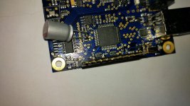
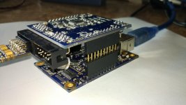
I made some measurements on the spectrum of a signal 11.025kHz + 229Hz_1LSB, I attached spectrums of a board with additional capacitor (digikey link: RR71A101MDN1 Nichicon | Capacitors | DigiKey) and without capacitor (stock board). I attached a pic with the test system: XMOS board, AK4490 and DRV603 board. The measurements are done with an EMU 0202 (little “mod”), so all the results are with addition error of the EMU and XMOS board.
PS: Since a while I haven’t got enough time as I want to. This probably will takes a few more months. If the rules are OK, could my son Lyuben to register and sometimes he to answer the questions (he is fully aware of the material and would be useful), of course we wouldn’t make traffic of the thread
Regards,
Joro
I like the concept of reclocking the i2s output from the XMOS after galvanic isolating it. But it doesn't work in this design unfortunately.
...
one would assume that reclocking would be very effective if the jitter of XMOS+isolator stays below 20 ns.
But what if it doesn't?... but for LR clock an error of 20 ns means that the next sample is delayed, very bad for Sound Quality.
To illustrate the normal work of the reclock it will be enough just to make simple measurement, for this purpose you will need at least 200MHz DSO and a limit test option (almost everyone DSO has this function).
If you haven’t got a DSO, maybe some basic mathematics will help:
Since you already read about the principle of working of the XMOS processor, you probably convinced yourself that the audio data are synchronously taken by external clock (has nothing in common with the XMOS PLL) in this case applied after galvanic isolation SI8661 with 350 picosec. p-p jitter. The last number have to be multiply by 2, cause MCLK is returned from the oscillator side – i.e. the absolute jitter:
XMOS jitter -> lower than 2picosec RMS (2picosec RMS ~ 30picosec p-p)
30+350+350 <800picosec p-p, so it’s much lower than 20ns. I hope that the numbers are enough to convince you that the reclock is no wrong if you haven’t convince d by measurement. Regarding reclock – it’s job is to reduce the jitter after galvanic isolation.
doc page 21
Error of 20ns of LRCLK – will lead to listen music with many tears and DSD128, 352.8kHz and 384kHz will be completely lost ………………
... Because the I2SoverUSB board isn´t immune to transport (different pc or USB cable), as was already ...
Incorrect. Obviously I haven’t explain well in post N:203 of this thread there are measurements of broadcasting of different USB cables, I’ll repeat myself on the exactly the same system changing just the cables, they have different behavior due to different construction and material. Different computers have different broadcasting ….
The EMI norms for the computers are enough for the environment, but no for Hi-Rez audio … the broadcasted disturbances/noises must be suppressed on the PC side! The disturbances/noises once putted in the “end system” have their influence on it, and there every track is and an antenna, which broadcast and receive from other tracks on the PCB board independently whether they are before or after the galvanic isolation.
That’s why the aim is not to let these disturbances/noises in the “end” device, but to reduce them outside the “end” device, where the struggle with them is much more effective.
AudioQuest JitterBug, Wyrd USB Decrapifier and others – Could you mount device for reducing disturbances/noises in the “end” device? Yes, but the price would be much higher (partition screened parts with expensive materials, duct capacitors and so on) than this to be made outside and it won’t be needed by anyone.
Ifi make and sell USB filter except the DACs, this doesn’t mean that their DAC are bad, it means that the engineers know where is the issue and know where exactly the struggle must be lead in order to be more effective and less expensive.
Accessory – iPurifier – there are a little more explanations
Accessory ? iPurifier2
The struggle with disturbances/noises is not easy at all, as somebody read 2-3 articles/papers and argue a little think it is. The specialized literature help in order to guide where and how to test your models and give some practical guidance. As a minimum a good spectrum analyzer and some additional tools, which one could make it yourself http://www.compliance-club.com/pdf/emctestingpart1.pdf after that a lot of tests are required till reaching satisfactory result. A simple screen sometimes helps in order of what we want to screen, but not always. For information RFI and EMI - Shielding and Absorbing Materials | RF/IF and RFID | DigiKey well there are and some specialized paints. ….
The certification and researches with accurate values can be made in special audio processed room 3 Meter EMC Test Chamber - Panashield Note: DSO software spectrum analyzer is not enough sensitive, but for a rough and fast rate in some cases may help.
As it’s about jitter I post a link where a material is systematized on Julian Dunn method about jitter and calculation of it.
Jitter explained - Part 1.4 [English]
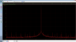
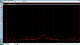
I made some measurements on the spectrum of a signal 11.025kHz + 229Hz_1LSB, I attached spectrums of a board with additional capacitor (digikey link: RR71A101MDN1 Nichicon | Capacitors | DigiKey) and without capacitor (stock board). I attached a pic with the test system: XMOS board, AK4490 and DRV603 board. The measurements are done with an EMU 0202 (little “mod”), so all the results are with addition error of the EMU and XMOS board.
PS: Since a while I haven’t got enough time as I want to. This probably will takes a few more months. If the rules are OK, could my son Lyuben to register and sometimes he to answer the questions (he is fully aware of the material and would be useful), of course we wouldn’t make traffic of the thread
Regards,
Joro
Attachments
I'm sure that NinoSimona will not 'improving' boards for some time..Do you have some measurements with and without cap..
Do you have another XMOS board for listening test and compare with 'improved' one..
It would be interesting to see is there any comment from J&L..
I'm sure that NinoSimona will not 'improving' boards for some time..
The problem are not the experiments (bottom line is a diy site, the main thing is that we have the opportunity to tweak around based on our knowledge level), rather how they are presented (the tone) and how the feedback is assimilated (usually from users with a superior knowledge level).
for me is much more interesting than reading hifi reviews for example, not to mention the opportunity to learn more.
Merry Christmas

..or wasting our and others time....bottom line is a diy site, the main thing is that we have the opportunity to tweak around based on our knowledge level..
.. this is diy site, but majority still believes in Santa Claus, knowlege and common sense are aside..
..or wasting our and others time..
.. this is diy site, but majority still believes in Santa Claus, knowlege and common sense are aside..
Indeed. It is DIY, but based on technology. Most of us want to learn more, and experiment - and for both, one needs a scientific approach.
..or wasting our and others time..
I don't agree it's been a waste of time. We've learned that increasing the filtering for the PLL doesn't make a measurable improvement. Every experiment teaches something, even the "failures".
Someone buy it with similar idea..Can you please post LCD controller board wiring diagram?
I'm wondering can I make it work with mine ak4490 based dac.
http://www.diyaudio.com/forums/digital-source/281271-diyinhk-ak4495-dac-6.html#post4518153
to add or not to add a capacitor
I'm quite surprised (or not?) by the fact some of you are so easily satisfied with some nice looking graphs...! They actually show little more than nothing w.r.t. the subject, but seem to be as effective as a sleeping pill.
But first, thank you joro for your comments and efforts to replicate my mod, much appreciated. In response to your post:
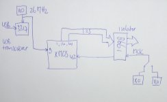
In this document of XMOS company, clock generation of the device is explained. An external clock, for this design a 26 Mhz clock (also used by USB transciever) on pin 9, is compared to an internal VCO (by PLL). This VCO's output is the base of switch clock,reference clock and XCore clock. The initial XCore clock is raised to 500MHz by setting F and D. This generated XCore clock is used to sample the external (isolated) audio clock, which is input on pin 42 and processed by 1 bit Hardware Response Port, as explained in this document. The acquired audio clock is then used by the logical core running the audio driver thread to generate BLCK, LRCK and clock DATA eventually. The process is asynchronous in nature due to this sampling.
The 2nd document defines XCore clock jitter as 70 ps, but obviously, since it's originally generated by VCO, the real jitter figure, and more important jitter distribution, is dependent on VCO stability. VCO output stability is dependent on stable and low noise power supply on PLL_AVDD pin, which is not guaranteed when it's tied to VDD, regardless the mild RC filter in between. And connecting the PLL pin to VDD is explicitly against datasheet recommendations.
Regarding the capacitor of your choice: Better not use an ultra low esr here, because with the 100n ceramic oscillation is possible.
-Regarding measurements-
The analysis you did is more or less a THD analysis, an attempt to measure the effect of jitter. This is by no means a reliable method to measure jitter IMO for several reasons, let me explain.
First of all, if we want to measure jitter in a system, we need to sample the digital i2s LRCK with very high frequency and accurate clock, and this will only be possible under laboratory conditions with excellent equipment. By doing so we can really say something reasonable about jitter. You made visible THD of the whole system, USB interface + DAC + analog stage + ADC : too much players in that game.
Second when doing a spectrum analysis, one makes visible what frequencies are present in the sampled waveform, with limited accuracy due to sampling rate (192kHZ) of ADC and FFT window width / points (?). When excessive jitter is present somewhere in the entire chain, the effect in frequency domain can be made a bit visible with spectrum analysis, as explained in the TNT-audio article written 10 years ago, but this doesn't isolate jitter in itself. By simply using an (inferior for this purpose) A/D audio card with low resolution, you aren't taking the jitter phenomena seriously.
Third: Just one single sine wave doesn't show you much when transferred to frequency domain by FFT, it really becomes interesting when a more complex waveform comprised of several sinusoids is analyzed. I wouldn't expect hearing any difference playing a dull sine wave with or without the cap mod either.
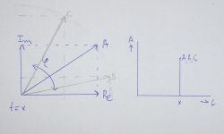
In facts: The graph of a spectrum analysis doesn't show the Fourier Analysis coefficients generated by the FFT algorithm, it doesn't show phase. Phase is of interest with respect to complex waveforms, i.e. with music. The coefficients are complex numbers / vectors, the amplitude at a certain (discrete) frequency is calculated by adding both vectors, SQRT(real^2 + imaginary^2). In the spectrum graph you see this result as the amplitude, see picture 2. This clearly induces that we can make numerous DIFFERENT waveforms, which will lead to different Fourier coefficients, but will show THE SAME amplitude at the same frequencies, and thus will show the same spectrum graph. Those different waveforms are yielding the same frequency components, but the sinusoids are differently related to each other by their respective phase.
So my point is: When jitter is considered as a timing problem, altering the original intended waveform slightly in some way in the time domain, this will also affect phase linearity in complex waveforms (in the frequency domain), a property of sound the human ear is very sensitive of. This would perhaps be more difficult to measure with low resolution FFT, but at least a spectrum graph doesn't show it. Preservation of phase is an important factor for reliable audio reproduction.
Instead of focusing on unintended harmonics in the spectrum, it would be better to focus on the intended harmonics and how their phase is affected. Even more because the amplitude of intended harmonics is far greater than that of unintended ones, and thus more likely to be audible.
The effect of the added capacitor isn't determined by this measurement, just as like a THD figure don't say much about Sound Quality.
Nino
I'm quite surprised (or not?) by the fact some of you are so easily satisfied with some nice looking graphs...! They actually show little more than nothing w.r.t. the subject, but seem to be as effective as a sleeping pill.
But first, thank you joro for your comments and efforts to replicate my mod, much appreciated. In response to your post:
Thanks for pointing me at the jitter math w.r.t. your design....
If you haven’t got a DSO, maybe some basic mathematics will help:
Since you already read about the principle of working of the XMOS processor, you probably convinced yourself that the audio data are synchronously taken by external clock (has nothing in common with the XMOS PLL) in this case applied after galvanic isolation SI8661 with 350 picosec. p-p jitter. The last number have to be multiply by 2, cause MCLK is returned from the oscillator side – i.e. the absolute jitter:
XMOS jitter -> lower than 2picosec RMS (2picosec RMS ~ 30picosec p-p)
30+350+350 <800picosec p-p, so it’s much lower than 20ns. I hope that the numbers are enough to convince you that the reclock is no wrong if you haven’t convince d by measurement. Regarding reclock – it’s job is to reduce the jitter after galvanic isolation.
doc page 21
Error of 20ns of LRCLK – will lead to listen music with many tears and DSD128, 352.8kHz and 384kHz will be completely lost ………………
...
In this document of XMOS company, clock generation of the device is explained. An external clock, for this design a 26 Mhz clock (also used by USB transciever) on pin 9, is compared to an internal VCO (by PLL). This VCO's output is the base of switch clock,reference clock and XCore clock. The initial XCore clock is raised to 500MHz by setting F and D. This generated XCore clock is used to sample the external (isolated) audio clock, which is input on pin 42 and processed by 1 bit Hardware Response Port, as explained in this document. The acquired audio clock is then used by the logical core running the audio driver thread to generate BLCK, LRCK and clock DATA eventually. The process is asynchronous in nature due to this sampling.
The 2nd document defines XCore clock jitter as 70 ps, but obviously, since it's originally generated by VCO, the real jitter figure, and more important jitter distribution, is dependent on VCO stability. VCO output stability is dependent on stable and low noise power supply on PLL_AVDD pin, which is not guaranteed when it's tied to VDD, regardless the mild RC filter in between. And connecting the PLL pin to VDD is explicitly against datasheet recommendations.
Regarding the capacitor of your choice: Better not use an ultra low esr here, because with the 100n ceramic oscillation is possible.
-Regarding measurements-
The analysis you did is more or less a THD analysis, an attempt to measure the effect of jitter. This is by no means a reliable method to measure jitter IMO for several reasons, let me explain.
First of all, if we want to measure jitter in a system, we need to sample the digital i2s LRCK with very high frequency and accurate clock, and this will only be possible under laboratory conditions with excellent equipment. By doing so we can really say something reasonable about jitter. You made visible THD of the whole system, USB interface + DAC + analog stage + ADC : too much players in that game.
Second when doing a spectrum analysis, one makes visible what frequencies are present in the sampled waveform, with limited accuracy due to sampling rate (192kHZ) of ADC and FFT window width / points (?). When excessive jitter is present somewhere in the entire chain, the effect in frequency domain can be made a bit visible with spectrum analysis, as explained in the TNT-audio article written 10 years ago, but this doesn't isolate jitter in itself. By simply using an (inferior for this purpose) A/D audio card with low resolution, you aren't taking the jitter phenomena seriously.
Third: Just one single sine wave doesn't show you much when transferred to frequency domain by FFT, it really becomes interesting when a more complex waveform comprised of several sinusoids is analyzed. I wouldn't expect hearing any difference playing a dull sine wave with or without the cap mod either.
In facts: The graph of a spectrum analysis doesn't show the Fourier Analysis coefficients generated by the FFT algorithm, it doesn't show phase. Phase is of interest with respect to complex waveforms, i.e. with music. The coefficients are complex numbers / vectors, the amplitude at a certain (discrete) frequency is calculated by adding both vectors, SQRT(real^2 + imaginary^2). In the spectrum graph you see this result as the amplitude, see picture 2. This clearly induces that we can make numerous DIFFERENT waveforms, which will lead to different Fourier coefficients, but will show THE SAME amplitude at the same frequencies, and thus will show the same spectrum graph. Those different waveforms are yielding the same frequency components, but the sinusoids are differently related to each other by their respective phase.
So my point is: When jitter is considered as a timing problem, altering the original intended waveform slightly in some way in the time domain, this will also affect phase linearity in complex waveforms (in the frequency domain), a property of sound the human ear is very sensitive of. This would perhaps be more difficult to measure with low resolution FFT, but at least a spectrum graph doesn't show it. Preservation of phase is an important factor for reliable audio reproduction.
Instead of focusing on unintended harmonics in the spectrum, it would be better to focus on the intended harmonics and how their phase is affected. Even more because the amplitude of intended harmonics is far greater than that of unintended ones, and thus more likely to be audible.
The effect of the added capacitor isn't determined by this measurement, just as like a THD figure don't say much about Sound Quality.
Nino
Attachments
Last edited:
Doesn't exist..The effect of the added capacitor..
So, we are all here dummies because we have more trust in man who designed excellent converter..I'm quite surprised (or not?) by the fact some of you are so easily satisfied with some nice looking graphs...! They actually show little more than nothing w.r.t. the subject, but seem to be as effective as a sleeping pill.
If you have enough knowledge why don't you design better device, instead of ''improving''..
It's been, definitely..I don't agree it's been a waste of time. We've learned that increasing the filtering for the PLL doesn't make a measurable improvement. Every experiment teaches something, even the "failures".
NinoSimona strikes again..
I'm quite surprised (or not?) by the fact some of you are so easily satisfied with some nice looking graphs...! They actually show little more than nothing w.r.t. the subject, but seem to be as effective as a sleeping pill.
But first, thank you joro for your comments and efforts to replicate my mod, much appreciated. In response to your post:
Thanks for pointing me at the jitter math w.r.t. your design.
In this document of XMOS company, clock generation of the device is explained. An external clock, for this design a 26 Mhz clock (also used by USB transciever) on pin 9, is compared to an internal VCO (by PLL). This VCO's output is the base of switch clock,reference clock and XCore clock. The initial XCore clock is raised to 500MHz by setting F and D. This generated XCore clock is used to sample the external (isolated) audio clock, which is input on pin 42 and processed by 1 bit Hardware Response Port, as explained in this document. The acquired audio clock is then used by the logical core running the audio driver thread to generate BLCK, LRCK and clock DATA eventually. The process is asynchronous in nature due to this sampling.
The 2nd document defines XCore clock jitter as 70 ps, but obviously, since it's originally generated by VCO, the real jitter figure, and more important jitter distribution, is dependent on VCO stability. VCO output stability is dependent on stable and low noise power supply on PLL_AVDD pin, which is not guaranteed when it's tied to VDD, regardless the mild RC filter in between. And connecting the PLL pin to VDD is explicitly against datasheet recommendations.
Regarding the capacitor of your choice: Better not use an ultra low esr here, because with the 100n ceramic oscillation is possible.
-Regarding measurements-
The analysis you did is more or less a THD analysis, an attempt to measure the effect of jitter. This is by no means a reliable method to measure jitter IMO for several reasons, let me explain.
First of all, if we want to measure jitter in a system, we need to sample the digital i2s LRCK with very high frequency and accurate clock, and this will only be possible under laboratory conditions with excellent equipment. By doing so we can really say something reasonable about jitter. You made visible THD of the whole system, USB interface + DAC + analog stage + ADC : too much players in that game.
Second when doing a spectrum analysis, one makes visible what frequencies are present in the sampled waveform, with limited accuracy due to sampling rate (192kHZ) of ADC and FFT window width / points (?). When excessive jitter is present somewhere in the entire chain, the effect in frequency domain can be made a bit visible with spectrum analysis, as explained in the TNT-audio article written 10 years ago, but this doesn't isolate jitter in itself. By simply using an (inferior for this purpose) A/D audio card with low resolution, you aren't taking the jitter phenomena seriously.
Third: Just one single sine wave doesn't show you much when transferred to frequency domain by FFT, it really becomes interesting when a more complex waveform comprised of several sinusoids is analyzed. I wouldn't expect hearing any difference playing a dull sine wave with or without the cap mod either.
In facts: The graph of a spectrum analysis doesn't show the Fourier Analysis coefficients generated by the FFT algorithm, it doesn't show phase. Phase is of interest with respect to complex waveforms, i.e. with music. The coefficients are complex numbers / vectors, the amplitude at a certain (discrete) frequency is calculated by adding both vectors, SQRT(real^2 + imaginary^2). In the spectrum graph you see this result as the amplitude, see picture 2. This clearly induces that we can make numerous DIFFERENT waveforms, which will lead to different Fourier coefficients, but will show THE SAME amplitude at the same frequencies, and thus will show the same spectrum graph. Those different waveforms are yielding the same frequency components, but the sinusoids are differently related to each other by their respective phase.
So my point is: When jitter is considered as a timing problem, altering the original intended waveform slightly in some way in the time domain, this will also affect phase linearity in complex waveforms (in the frequency domain), a property of sound the human ear is very sensitive of. This would perhaps be more difficult to measure with low resolution FFT, but at least a spectrum graph doesn't show it. Preservation of phase is an important factor for reliable audio reproduction.
Instead of focusing on unintended harmonics in the spectrum, it would be better to focus on the intended harmonics and how their phase is affected. Even more because the amplitude of intended harmonics is far greater than that of unintended ones, and thus more likely to be audible.
The effect of the added capacitor isn't determined by this measurement, just as like a THD figure don't say much about Sound Quality.
Nino
So true, whilst measurement's and science based engineering work in all other fields of electronics, this is high end audio where only our ears and fallible perception counts...
What you have to ask yourself is how much of a problem is jitter these days and if it is controlled at the point of conversion (the only place it does matter).
- Status
- This old topic is closed. If you want to reopen this topic, contact a moderator using the "Report Post" button.
- Home
- Source & Line
- Digital Line Level
- XMOS DSD 384 kHz / 32bit USB