I don't have the proper equipment to do these measurements. But improvement is so obvious, I don't think figures are needed to prove the better performance, though measurements would be nice to verify my theory...
What parameters do you think are improved? Measuring noise and jitter only requires a basic PC with a half-way decent soundcard...
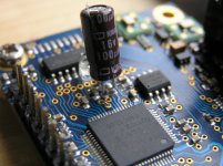
Hi Spartacus, no, Vdd is applied externally, onto 8 pins around the chip. Yes, it's an R, the filter is recommended in datasheet page 17 of the XMOS device used. The regulation is only a problem when there's variable current demand.
Measurements are essential argument..But improvement is so obvious, I don't think figures are needed to prove the better performance, though measurements would be nice to verify my theory..
Maybe XMOS board now have lower performance, but you think that sounds better..
What a silly viewpoint, you are manipulating digital signals without measurement's you have NO idea what you are doing.... Digital when wrong does not have a subtle effect on the sound, and neither do minor changes to the digital system have subtle effects on the resultant soundfield (other than possible jitter reduction at the point of conversion).
All you have done is add a larger value capacitor at some point in the circuit (contrary to the data sheet recommendation for the supply in question.), you have no empirical evidence that it is doing anything positive to the design... You may call this DIY I just call it playing...
All you have done is add a larger value capacitor at some point in the circuit (contrary to the data sheet recommendation for the supply in question.), you have no empirical evidence that it is doing anything positive to the design... You may call this DIY I just call it playing...
What a silly viewpoint, you are manipulating digital signals without measurement's you have NO idea what you are doing....
"If it looks good it must sound good"
")
You may call this DIY I just call it playing...
For many, their DIY hobby *is* just playing around, and nothing wrong with that. It just doesn't teach us much.
Well at least someone is soldering something and listening to it instead of typing on a keyboard.
+1 LOL
Well at least someone is soldering something and listening to it instead of typing on a keyboard.
Not sure, seems a heck of a lot of people are typing (and posting pictures) instead of trying to understand how the equipment actually works...
Not sure, seems a heck of a lot of people are typing (and posting pictures) instead of trying to understand how the equipment actually works...
Hi Julf,
You're 100% right but sometimes good to have a little fun, but you're right
Do
You're 100% right but sometimes good to have a little fun, but you're right
If we aren't having fun, what's the point of DIY?
Hi marce, I don't mind what you call this at all and disagree with you. Why don't you comment on my explanation in my post, other than stating your opinion about what you think I'm doing, I think that's rather short sighted. I didn't manipulate 'digital' signals by adding the cap, it's just improving analog psu of PLL, please spare me your dogmas about minor changes to a digital system...What a silly viewpoint, you are manipulating digital signals without measurement's you have NO idea what you are doing.... Digital when wrong does not have a subtle effect on the sound, and neither do minor changes to the digital system have subtle effects on the resultant soundfield (other than possible jitter reduction at the point of conversion).
All you have done is add a larger value capacitor at some point in the circuit (contrary to the data sheet recommendation for the supply in question.), you have no empirical evidence that it is doing anything positive to the design... You may call this DIY I just call it playing...
I didn't say effects were subtle either, and by the way: we are talking about jitter reduction here indeed, you got that right!
There are more designs just simply copying datasheet design recommendations, while in this case datasheet is very clear about PLL_AVDD to be separated from VDD, with the additional use of RC-filter of recommended proportions. Just complying to recommendation won't mean you have the best design, although in this case it would be with psu separated, as stated by datasheet. By adding the cap we can try to compensate for the original error of not separating power supplies, it's just as simple as that.
@Julf: I think you just invited yourself to teach us a lesson on how this equipment really works, please go ahead, would be informative and fun tooJulf; said:Not sure, seems a heck of a lot of people are typing (and posting pictures) instead of trying to understand how the equipment actually works...
Funny, I recently switched to using glueWell at least someone is soldering something and listening to it instead of typing on a keyboard.
I didn't manipulate 'digital' signals by adding the cap, it's just improving analog psu of PLL, please spare me your dogmas about minor changes to a digital system...
I didn't say effects were subtle either, and by the way: we are talking about jitter reduction here indeed, you got that right!
In that case, it ought to be pretty easy to see how much the jitter performance actually improved, and what the audible effect is.
AES E-Library The Diagnosis and Solution of Jitter-Related Problems in Digital Audio Systems@Julf: I think you just invited yourself to teach us a lesson on how this equipment really works, please go ahead, would be informative and fun too
OK, why should we all loose time talking about technicals when we can simply try out the mod Ninosimona suggests?
I think we would save some time and be much more sure about its results than discussing about each one's interpretation of a datasheet or a technical guide...
In my opinion that's the REAL scientific way: first experimenting, then building a theory to justify the results. Not the reverse (that is called FAITH).
Unfortunately my system is down and under rework now, but i guess all of you have an I2SoverUSB board under his hands. The mod is quite easy and fast to accomplish (and remove), so could someone please try it and report his SQ findings and jitter measurements?
Well at least someone is soldering something and listening to it instead of typing on a keyboard.
Actually somebody is laying out PCB for a medical ventilator, doing the cough detection system, low level analogue from the sensors with DACs then to a microprocessor for analysis... thinking about boring things such as signal integrity (trace effects especially on low level analogue signals), EMC issues, power supplies layout and location on board (Keep the SMPS switching nodes out of the way etc.)...
So how can soldering one large value cap onto the design change the sound so dramatically, without careful measurement's along the digital chain how do you quantify what is happening. Large value caps act as reservoir capacitors in the digital decoupling scheme, they cannot react fast enough for the switching, but act as reservoirs to top up the smaller value caps local to a devices pins, so a start would be monitoring the power supply pin under load conditions...
There are more designs just simply copying datasheet design recommendations, while in this case datasheet is very clear about PLL_AVDD to be separated from VDD, with the additional use of RC-filter of recommended proportions. Just complying to recommendation won't mean you have the best design, although in this case it would be with psu separated, as stated by datasheet. By adding the cap we can try to compensate for the original error of not separating power supplies, it's just as simple as that.
You may find this surprising but IC data sheets tend to show the BEST practice for using that device, this is because the IC manufacturers want you to use their device with minimal problems...
Without any measurements you have no proof of anything happening, just hearsay though...
OK, why should we all loose time talking about technicals when we can simply try out the mod Ninosimona suggests?
I think we would save some time and be much more sure about its results than discussing about each one's interpretation of a datasheet or a technical guide...
In my opinion that's the REAL scientific way: first experimenting, then building a theory to justify the results. Not the reverse (that is called FAITH).
Unfortunately my system is down and under rework now, but i guess all of you have an I2SoverUSB board under his hands. The mod is quite easy and fast to accomplish (and remove), so could someone please try it and report his SQ findings and jitter measurements?
Funny that's the opposite way to how the designs I work on in electronics are done... lots of boring working out the solution to the design requirement, some experimentation is part of the cycle, but it is considered experimentation with measurement's to determine the results!
In my opinion that's the REAL scientific way: first experimenting, then building a theory to justify the results. Not the reverse (that is called FAITH).
Absolutely! But after formulating a theory, the next step is to postulate an experiment that can validate or invalidate the theory. And in fact, before formulating a theory, one should first validate the observations.
If you hear a difference, there are multiple explanations and theories. At the most basic level, there might be a real, physical difference, but it might also be that the perceived difference is caused by confirmation bias. Thus the first thing to do is to isolate the effect of bias. Fortunately there is a relatively easy way to do that, by using a double-blind listening test.
- Status
- This old topic is closed. If you want to reopen this topic, contact a moderator using the "Report Post" button.
- Home
- Source & Line
- Digital Line Level
- XMOS DSD 384 kHz / 32bit USB