Nelson Pass said:The MOX discrete stage was reverse engineered...
I beg the difference... INSPIRED, not reverse engineered
") . The truth be told, I was just as equally inspired by Mr Borbely's work (for example, see Fig.2, page 10, audioXpress 3/05)... and the work of Revox-Studer-Tascam designers from the '80s.
. The truth be told, I was just as equally inspired by Mr Borbely's work (for example, see Fig.2, page 10, audioXpress 3/05)... and the work of Revox-Studer-Tascam designers from the '80s. Reverse engineering would be, for example, me COPYING ugs3 'as is' after I have seen its original schematic and all the component values in it... and then calling it, say, MUGS3
. Regards,
Milan
From the web:
"Hardware reverse engineering involves taking apart a device to see how it works. For example, if a processor manufacturer wants to see how a competitor's processor works, they can purchase a competitor's processor, disassemble it, and then make a processor similar to it. However, this process is illegal in many countries. In general, hardware reverse engineering requires a great deal of expertise and is quite expensive." (http://whatis.techtarget.com/definition/0,289893,sid9_gci507015,00.htm=
...or what we called here MUGS3
MOX has nothing to do with the above definition.
Regards,
Milan
Inspired...
I tested the cascode version with different values for R1-R4. Measured with single ended input and single ended output:
R1=R2=248 Ohm
R3=R4=221 Ohm
freq.response -3dB at 144kHz
Gain 18,4dB, max. output voltage (no clipping) >11Veff
R1=R2=124 Ohm
R3=R4=100 Ohm
freq.response -3dB at 144kHz
Gain 19,88dB, max. output voltage (no clipping) >11Veff
R1=R2=55 Ohm
R3=R4=50 Ohm
freq.response -3dB at 140kHz
Gain 20,36dB, max. output voltage (no clipping) 7Veff
R1=R2=22 Ohm
R3=R4=0 Ohm
freq.response -3dB at 95kHz
Gain 20,00dB, max. output voltage (no clipping) 6Veff
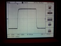
My favorite (now) is 124/100 Ohm.
Adam
Pic: square wave at 10 khz (124/100 Ohm)
I tested the cascode version with different values for R1-R4. Measured with single ended input and single ended output:
R1=R2=248 Ohm
R3=R4=221 Ohm
freq.response -3dB at 144kHz
Gain 18,4dB, max. output voltage (no clipping) >11Veff
R1=R2=124 Ohm
R3=R4=100 Ohm
freq.response -3dB at 144kHz
Gain 19,88dB, max. output voltage (no clipping) >11Veff
R1=R2=55 Ohm
R3=R4=50 Ohm
freq.response -3dB at 140kHz
Gain 20,36dB, max. output voltage (no clipping) 7Veff
R1=R2=22 Ohm
R3=R4=0 Ohm
freq.response -3dB at 95kHz
Gain 20,00dB, max. output voltage (no clipping) 6Veff
My favorite (now) is 124/100 Ohm.
Adam
Pic: square wave at 10 khz (124/100 Ohm)
Attachments
acaudio said:For test I think about a replacement of IRFD110/9110 with IRF610/9610 with higher bias.
I think this is a good idea. IRFD110 must be the very same chip as IRF510, if you compare the datasheet. Therfore, going to IRF610 / 9610 can't be wrong at all (and you get a much more robust part in respect of power dissipation...)
Well, I believe that Jocko didn't exclude J-FET's, as they are too isolating the gate from drain/source. And.....don't underestimate Jocko's experience as a designer...acaudio said:I believe more to statement from really developers , which use fets since more tens of years, they should know it. Such as Mr.Pass or Mr. Borbely. At the moment I have no really good idea, which would be so simple and good as cascoding jfet by jfet. In figure of noise anyway.
Anyway, thanks for posting your measuring results.
Maybe, if you would go lower than 100/124 Ohms for R1-R4, you could lower R6-R9, to keep the same bias voltage for the MOSFET Gates and not increasing open loop gain.
As you would like to go higher with current for Q7-Q10, I think you are forced to decrease R18-R21. This will increase open loop gain.
Will you lower R16 - R17 in this case?
Just some thinking....don't want to bother you...
Ciao, Tino
Nelson Pass said:I often buy as much as a 5 year supply of critical parts. As long
as you know you'll use them, it's an excellent investment.
This is very true also in other industries, but unfortunately, especially in big companies, the bosses seem to have a hobby: low inventories!
And in small companies, the only drawback of having big inventory is, that they often lack liquidity....

Well, back to audio now....
In the U.S. inventory at a company shows up at the end of the year as income and is taxable. Parts inventory becomes an expense only when final goods ship (or the parts are scrapped). If you borrow money to buy the parts then you pay interest on the money until it's paid back plus the loan ends up as taxable income which it normally wouldn't.
One needs to have compelling motivation to take on a large inventory.
The state of California used to have a special inventory tax on inventory present on Dec.31st. There was a serious industry carting things to storage warehouses in Nevada in late December and carting them back to California in early January. It mostly affected retailers and I think it went away quite a while ago.
GL
moamps said:I beg the difference... INSPIRED, not reverse engineered
I am happy to acknowledge the distinction.
zinsula said:
I think this is a good idea. IRFD110 must be the very same chip as IRF510, if you compare the datasheet. Therfore, going to IRF610 / 9610 can't be wrong at all (and you get a much more robust part in respect of power dissipation...)
Well, I believe that Jocko didn't exclude J-FET's, as they are too isolating the gate from drain/source. And.....don't underestimate Jocko's experience as a designer...
Anyway, thanks for posting your measuring results.
Maybe, if you would go lower than 100/124 Ohms for R1-R4, you could lower R6-R9, to keep the same bias voltage for the MOSFET Gates and not increasing open loop gain.
As you would like to go higher with current for Q7-Q10, I think you are forced to decrease R18-R21. This will increase open loop gain.
Will you lower R16 - R17 in this case?
Just some thinking....don't want to bother you...
Ciao, Tino
I´m no sure, whether we should lower the values of R1-R4 as aprox. 100 Ohm. Lower values gives higher open loop gain, but a higher input capacitance and higher distortion.
Lower values of R6-R8 gives more voltage loss at Q1-Q4 and more power dissipation at each JFET, we should have a look at.
In my opinion, for biasing of Q7-Q10 we should have a voltage loss across R6-R9 aprox. 10V, the value of output stage bias is then adjustable with value of R18-R21. I would mean, a power dissipation at Q7-Q10 by using of IRFD110/9110 should be lower than 0,6W each. I think 1k as value for R16/R17 is low enough.
In the true, I was a little confused, than Mr.Pass wrote to me:
"...and we run them at very low values, so as to mostly create level translation." For me -> high open loop gain. I thought, a lower open loop gain are better for susy?
Mr. Pass, what is right?
Best Regards
Adam
Oh, yes, I forgot that dissipation issue...acaudio said:Lower values of R6-R8 gives more voltage loss at Q1-Q4 and more power dissipation at each JFET, we should have a look at.

Maybe it would distribute the dissipation better if it would be possible to increase the voltage between source of Q3 and drain of Q1 (and Q4 and Q2)? But then, a voltage reference (LED, Diode, ...) between source of Q1 and gate of Q3 would be needed. Don't know if it has adverse effects on sound quality.
Regarding the input capacitance, I believe you still got the minimum possible, as you are cascoding the devices.
Ciao, Tino
Tino,
I believe, both cascode and Rs are added in their positive effect.
Mr.Borbely wrote in his articles "... the input capacitance of the circuit [previously 600pF-Adam] is aprox. 160pF, so the cascoding indeed reduces the input cap... further reduction is archived by adding local feedback Rs... the input capacitance is now reduced to 50pF ..."
Adam
I tested a higher output stage bias, circuit with 100/124 Ohm and R18-R21=221 Ohm, and R18-R21=390Ohm
with 390 Ohm the square wave at 10 khz is more "square" as with 470 Ohm, with 221 Ohm is less "square" as the both.
New favorite -> R18-R21=390Ohm
I tested just too this configuration:
R1=R2=22 Ohm
R3=R4= 0 Ohm
R6-R8=2k
R18-R21=390 Ohm
Ijfet=4,5mA
The measurements are worse as previous with 100/124 Ohm
Freq. resp. -3dB at 100khz (100/124, 144kHz)
Adam
I changed the offset adjustment (thanks Metalman). It works now perfect. I tested too the stage with IRF610/9610, but it works not so good as with IRF110/9110, bandwidth only 100kHz...
I received today the 389 BL types, so a stereo version may be built.
Here the actually schematic.
With this values it should work good.
Input should be AC coupled, capacitors at output are not needed.
Regards
Adam
I received today the 389 BL types, so a stereo version may be built.
Here the actually schematic.
With this values it should work good.
Input should be AC coupled, capacitors at output are not needed.
Regards
Adam
Attachments
acaudio said:I tested too the stage with IRF610/9610, but it works not so good as with IRF110/9110, bandwidth only 100kHz...
Now this puzzles me quite a bit.....both the IRF610 and the 9610 have lower capacity values that the IRFD110/9110 combo.
What else can influence the bandwith? (Assuming that R6-R9 did not have been changed when swapping the MOSFET's).
Tino/Going back to his work...hoping that he understand it better than electronics

zinsula said:
Now this puzzles me quite a bit.....both the IRF610 and the 9610 have lower capacity values that the IRFD110/9110 combo.
What else can influence the bandwith? (Assuming that R6-R9 did not have been changed when swapping the MOSFET's).
Tino/Going back to his work...hoping that he understand it better than electronics
Hi Tino,
I was too confused, but:
1) my 610/9610 are Fairchild and not original IRF, maybe they have another characteristic.
2) with the same value of R18-R21=390 Ohm it works very similar to 110/9110, bandwidth ~140kHz
3) the way to use 610/9610 was a wish to higher current, I tested it with R18-R21 =100 Ohm, I~70mA ,the devices runs very hot, the effect: much higher gain, but small bandwidth.
So I remain for the time being with IRF110/9110.
Best Regards
Adam
thomasfw said:Dear Adam & all,
I still interest in waiting for "Human Listening" test !
We all should know the normal "ear" response is only
20 - 20k hz !
Best Regards !
Thomas
"HL" coming soon...
It´s a lot of work...
thomasfw said:Dear Adam & all,
I still interest in waiting for "Human Listening" test !
We all should know the normal "ear" response is only
20 - 20k hz !
Best Regards !
Thomas
IT PLAYS MUSIC ! My first impression, it is a thunderstorm!
Pure dynamic.

More later
Best Regards
Adam
- Status
- This old topic is closed. If you want to reopen this topic, contact a moderator using the "Report Post" button.
- Home
- Amplifiers
- Pass Labs
- X2_ugs3,4