samsagaz said:Someone have the correct Mouser/Digikey BOM?
I think that will depend on the board layout Peter comes up with.
This amp puts out 2amps or 100W a channel, and the 1 ohm resistors also really belt out heat.
I think a thick film resistors attached to the heatsink replacing these would save space and keep from melting the boards.
C4 needs to be large enough to avoid turn on thud, bad for FR speakers... I use 33,000uf
We know what the power supply looks like, it uses 4 X 1 ohms vs 4 X .47 ohms like the F3-F5, and Peter already has those around to view.
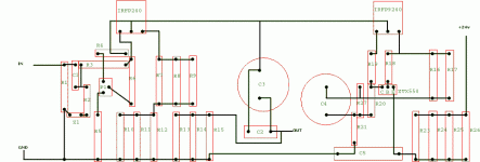
Here is the board layout I used, stolen from other thread.
Attachments
Peter Daniel said:I will have it finalized this week.
any news on this layout?
- Status
- This old topic is closed. If you want to reopen this topic, contact a moderator using the "Report Post" button.
- Home
- Group Buys
- WTB Firstwatt Clone F2 PCB boards

