Hello All,
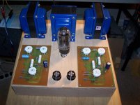
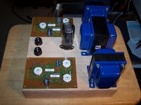
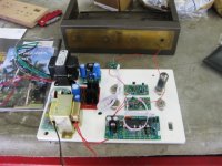
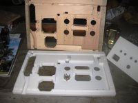
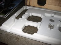
I would like comments on the project I'm working on. I am building an 6BQ5
push/pull amp and I am making an all wood chassis. What pit-falls should I
look for?
For a little history on the amp, see post #72 here.
http://www.diyaudio.com/forums/tube...ircuit-referenced-tubecad-journal-site-8.html
Thanks.
Attachments
Hello Bruce,
A totally wooden chassis is a nifty way of making an amp since, I like wood. And aside from the lack of any shielding that a metal chassis would provide, I still like the idea and may do one myself if I live long enought to get around to it. But I can think of one thing.
If I were making this, I would provide for a safty ground system below the wood top plate just as there would be with a metal chassis. Perhaps a wide piece of sheet copper below the transformers. That is, one wide enough to span all three transformers with appropriate holes for both the wires and all the mounting bolts. I'd make sure that at least one bolt of each transformer made a good and proper contact with the metal end shell by removing some paint from the mounting foot. Then this collective ground connection would connect to the mains third wire ground.
If a copper sheet is not to your liking, then I suppose aluminum would work too. Or even a heavy solid copper buss wire connecting each transformer from below, and grounding it, would serve the same purpose. Remember it's for safety reasons incase a transformer develops leakage, or even a short to the core. Doesn't happen often, but it could.
Hi,
Just for interest, They work great this one is silent")
Its been posted before, I use double sided PCB and aluminium foil.
Just use all the usual twisted heaters etc.
Remember to earth your transformers and all metal parts..Thats why I used a ground plane.
So you could cover the inside of the top with pcb, just take precautions for eddy currents and if you take an AC cable through the ground plane bring the return back though the same hole. Cut any holes and slit the copper to the outside of the board. I prefer wood chassis
Regards
M. Gregg
Just for interest, They work great this one is silent
Its been posted before, I use double sided PCB and aluminium foil.
Just use all the usual twisted heaters etc.
Remember to earth your transformers and all metal parts..Thats why I used a ground plane.
So you could cover the inside of the top with pcb, just take precautions for eddy currents and if you take an AC cable through the ground plane bring the return back though the same hole. Cut any holes and slit the copper to the outside of the board. I prefer wood chassis
Regards
M. Gregg
Attachments
Last edited:
Aluminium chassis' have virtually no shielding effect, almost transparent to EM fields. Substances can be either reflective or absorptive to EM....The trick way is to make a two layered chassis....copper on the inside to absorb EM and Stainless Steel on the outside to reflect EM....what EM gets thru the copper reflects off the SS to make a second pass thru the copper.
_____________________________________________________Rick.......
_____________________________________________________Rick.......
Thin aluminium has a huge shielding effect for electric fields, but little for low frequency magnetic fields. Any metal (any good conductor, in fact) will do this for electric fields.
To absorb 'EM' you don't use copper but a resistive material which matches the impedance of free space. Copper reflects 'EM' very efficiently. Stainless steel possibly slightly less so as it is not quite such a good conductor.
To absorb 'EM' you don't use copper but a resistive material which matches the impedance of free space. Copper reflects 'EM' very efficiently. Stainless steel possibly slightly less so as it is not quite such a good conductor.
Depending on circumstances your hifi might suffer from the reception of signals. Most coming from radiostations, cell phones, computers and energy saving light bulbs. Despite all theory there's no need shielding your case with metal as the tubes themselves are sticking out. Neither thin steel, aluminium or copper is preventing 50 or 100Hz magnetic fields to pass. Wood is a good material for building an AF amplifier case. Just take care of disturbing signals and limit the bandwith to frequencies of interest.
Timely thread. This build is a remote controlled tube preamp. I used my Shopbot CNC to machine a plywood chassis to fit inside an empty Eico metal amp enclosure. I was dreading painting it, worried about temperature issues, etc.
Then a light bulb went on -- use Corian. Corian scraps (especially the part cut out for the sink) can be aquired for cheap or free and machines even easier than wood.
This was pure white Corian. Now I want to get more "artistic" with an amp that looks like it was mounted on a "granite" chassis.
Then a light bulb went on -- use Corian. Corian scraps (especially the part cut out for the sink) can be aquired for cheap or free and machines even easier than wood.
This was pure white Corian. Now I want to get more "artistic" with an amp that looks like it was mounted on a "granite" chassis.
Attachments
Last edited:
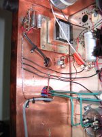
I like to line the internal structure of the wood chassis with copper foil tape, cheap and readily available from McMaster Carr. Solders very easy for a "chassis" type of enclosure. Not shown in the picture, but I also wrap over the lip of the wood, where the top panel rests, so there is contact there, no gaps. Underside of panel is chromated, so there is low resistance.
You can get this copper foil tape with or without conductive adhesive. The conductive style is pricey, so I only use it for grounding cores and maybe capacitor cans as needed (shown in picture on input transformer).
The bottom of the enclosure is of course open, but it also is resting on a steel shelf in my rack, so on a practical level the internals are fairly well shielded from EMI. Nothing is perfect, and as has been mentioned above, the tubes themselves are sticking out in the open.
I see no need for magnetic shielding; my designs are all separate power supplies with 60Hz transformers physically separated from the amplifier proper. I have found this to be so much easier than trying to shield power frequency magnetic fields from an interstage, output xfmr, or triode grid.
Attachments
I have made a few amps with an all wood chassis, and two with clear Lexan (Plexiglass melts!). In both Lexan amps I just used a ground wire from the transformers to the PC board. In the wooden amps I stapled a piece of copper screen from Michaels Arts and Crafts to the under side for a ground plane. All amps were hum free. A good PCB layout and grounding scheme is a must.
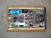
I have had so so luck doing pcbs...this circuit was simple enough that I wanted to try p2p and it worked great.
You might have better luck with a wooden frame and aluminum top plate.
I look forward to your results...that was my post in the op..
Looks like you are off to a good start.
This is still one of my favorite amps. Along with George's sse and the moskido.
You might have better luck with a wooden frame and aluminum top plate.
I look forward to your results...that was my post in the op..
Looks like you are off to a good start.
This is still one of my favorite amps. Along with George's sse and the moskido.
If you use a ground plane,
I would split it in two halves with a 3mm gap between, one half under the Tx's and the other for the electronics. Take each half to a star Gnd.
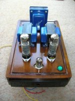
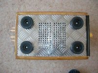
I used aluminium checker plate for the base. Also a single hole at the back of the amp to vent the heat "driven" by the heat from the choke.
Diodes were HEXfred and coupling caps were Mundorf silver/oil..if I built it again I would use Hovland super caps..The amp was SE so to reduce 2nd harmonic the choke was bypassed. Very quiet like the speakers are not connected. Finish was shellac resin <<if your mad enough to use it.
I have been thinking what kind of strange chassis you could make with wood..an amp I saw in a mag a while back was called the valve engine and was built like a V8 ..
Just for fun.
Regards
M. Gregg
I would split it in two halves with a 3mm gap between, one half under the Tx's and the other for the electronics. Take each half to a star Gnd.
I used aluminium checker plate for the base. Also a single hole at the back of the amp to vent the heat "driven" by the heat from the choke.
Diodes were HEXfred and coupling caps were Mundorf silver/oil..if I built it again I would use Hovland super caps..The amp was SE so to reduce 2nd harmonic the choke was bypassed. Very quiet like the speakers are not connected. Finish was shellac resin <<if your mad enough to use it.
I have been thinking what kind of strange chassis you could make with wood..an amp I saw in a mag a while back was called the valve engine and was built like a V8 ..
Just for fun.
Regards
M. Gregg
Attachments
Last edited:
Timely thread. This build is a remote controlled tube preamp. I used my Shopbot CNC to machine a plywood chassis to fit inside an empty Eico metal amp enclosure. I was dreading painting it, worried about temperature issues, etc.
<snip>
Tom, just wanted to say this looks incredibly cool. I keep thinking that perhaps someday I will convert my mini-mill for CNC.
Member
Joined 2009
Paid Member
tin foil can be good for shielding all sorts of things.... Aluminum Foil Deflector Beanie
The box is very strong. I used 1/2" Birch plywood, glue and dowl pegs. No nails. I will use zinc plated 16 ga sheet metal under the transformers connected to earth thru the 3 prong socket from the AC mains. I also plan on having a 12 ga copper wire running from the front of the amp to the rear as a common ground. I will have a 1 meg resistor between common ground and earth.
Thanks to all for your comments.
Thanks to all for your comments.
- Status
- This old topic is closed. If you want to reopen this topic, contact a moderator using the "Report Post" button.
- Home
- Design & Build
- Construction Tips
- Wood chassis