I still can't make the references out on the circuit, but it is these resistors. You are measuring the voltage across them. The current will be essentially similar in each for a given channel. Just be careful not to short anything out as one of them has 40 volts on it.
Attachments
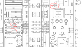
and you are measuring the DC voltage across that resistor.
As opposed to measuring from a resistor leg against ground?
Jan
If I'm reading this right it is the 500 ohm resistor that's next to the variable resistor, I can them add another resistor to the 500 ohm resistor say 2K2 and see what the value is across the 1ohm emitter and this should give me a good indication of what size resistor to fit in place of the 500 ohm to get the bias down to say 36MV. Would this also work in reverse for the other channel to increase it from 15MV to 36MV. Thanks
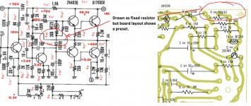
I'm just looking at the board layouts and that variable resistor you mention isn't drawn as such on the circuit diagram, its drawn as a conventional resistor... hence me saying it was a fixed bias amp.
That variable resistor actually sets the bias current so you have the means to adjust it already present, its just that the circuit diagram is drawn incorrectly.
That variable resistor actually sets the bias current so you have the means to adjust it already present, its just that the circuit diagram is drawn incorrectly.
Yes, this one adjusts the bias current in the output transistors. What we still don't know is the official figure. The other preset adjusts the 'midpoint' voltage which is the DC voltage at the amplifier end of those speaker coupling caps you replaced. Its normally set to one half the value of the supply voltage to ensure the output can swing equally above and below this point. So if the supply is 83 volts then you would adjust it to give 41.5 volts at the output. Its not critical and a couple of volts either way makes no difference.
The bias current is far more important to get right because you must avoid at all costs 'thermal runaway' which is where the current rises destructively. The lower the current, the less the risk.
Without a figure to work to we must ensure that there is sufficient bias when the amp is cold and not to much when its really hot... so its a compromise. I would initially turn it down to match the other channel and then see how both channels compare hot vs cold.
Attachments
So am I right in thinking that two trim pots are for bias and two for DC offset. Thanks
Yes, one pot for bias (the one shown above) and one for 'midpoint' for each amplifier board. The 'midpoint' is not DC offset, what you are measuring and setting is the voltage at the main amplifier output before the speaker coupling caps.
The two adjustments won't interact.
As all this is new to you I would suggest this...
Its not easy holding meter leads and adjusting trimmers at the same time so solder a couple of wires to each resistor and feed those to the meter so that you can watch it unattended.
Tweak the bias pot a fraction each way, no more and observe the reading. If nothing happens then you are probably monitoring one channel and adjusting the other. If the reading adjusts as expected then go ahead and make the adjustment.
Make sure any open ended wires you may attach are out of the way and insulated if not in use. No shock hazard but one instant of a short to something and it all goes pop.
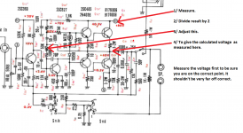
The midpoint volts can be set more easily. Just connect the black meter lead to chassis and measure the DC rail voltage. Divide that figure by 2 and adjust each channels 'midpoint preset' to give the calculated voltage as measured on the positive end of the speaker coupling caps or on the 'other' 1 ohm that joins the two transistors. Either point will give the same reading.
Its not easy holding meter leads and adjusting trimmers at the same time so solder a couple of wires to each resistor and feed those to the meter so that you can watch it unattended.
Tweak the bias pot a fraction each way, no more and observe the reading. If nothing happens then you are probably monitoring one channel and adjusting the other. If the reading adjusts as expected then go ahead and make the adjustment.
Make sure any open ended wires you may attach are out of the way and insulated if not in use. No shock hazard but one instant of a short to something and it all goes pop.
The midpoint volts can be set more easily. Just connect the black meter lead to chassis and measure the DC rail voltage. Divide that figure by 2 and adjust each channels 'midpoint preset' to give the calculated voltage as measured on the positive end of the speaker coupling caps or on the 'other' 1 ohm that joins the two transistors. Either point will give the same reading.
So if I turned the high side down to 15MV same as the other channel which I thought sounded well and did not get too hot that should be fine. The midpoint is that a case of testing the voltage across the coupling caps. The original caps were 75v and I think I read that the voltage should never exceed 75% of that. So 75% of 75/2 = 28.1v would this be a ballpark figure I'm a long way off working the maths out properly. Thanks
Yes, turn the bias on the high side down to match the other channel.
Midpoint") err... not quite.
err... not quite.
Look at the circuit diagram. Do you see where it says 80 volts. That is the main supply voltage the amp runs on. You measure that voltage and divide it by two. Now look where it says 40 volts on the diagram which is on the collector of the lower output transistor. That is the voltage you adjust to be the same as the value you just calculated. You measure this voltage from ground (chassis) to the point of interest.
That's me done for tonight... if you are not sure then wait and ask. Its not worth risking damaging anything
Midpoint
err... not quite.Look at the circuit diagram. Do you see where it says 80 volts. That is the main supply voltage the amp runs on. You measure that voltage and divide it by two. Now look where it says 40 volts on the diagram which is on the collector of the lower output transistor. That is the voltage you adjust to be the same as the value you just calculated. You measure this voltage from ground (chassis) to the point of interest.
That's me done for tonight... if you are not sure then wait and ask. Its not worth risking damaging anything
Attachments
Hello Thank you for help. I have just adjusted the bias its now 16MV across both the 1ohm emitter resistors.( it sounds very good) As for the midpoint would I be right in says that its half the mains supply and I put the black anywhere on the chassis and the red to the + side on one of the coupling caps and adjust the correct trimpot (I know which one) to the value of half the mains. Thanks.
Its not half the mains voltage, its half the DC supply voltage the amp runs on which is shown as nominally +80 volts DC. So you need to measure that value first.
An easy point to check both that voltage and the midpoint is actually the metal case of the two output transistors. One will be at around 80v and the other around half that.
Just be careful not to short anything.
An easy point to check both that voltage and the midpoint is actually the metal case of the two output transistors. One will be at around 80v and the other around half that.
Just be careful not to short anything.
Thank you for your help I have done what you said to do for the midpoint it was 79.2V on both sides so I set both sides to half that figure. I found out that the bias should be between 20-40MA for this amp so I used OHMS law to work this out from the voltage which easy because it is a 1OHM resistor. I will recap the rest of the amp in time but for now I'm going to enjoy the amp. You have learnt me a lot THANK YOU for your time and wisdom.
- Status
- This old topic is closed. If you want to reopen this topic, contact a moderator using the "Report Post" button.
- Home
- Amplifiers
- Solid State
- Will increaseing coupling caps cause problems