The bias on this amp is fixed, with no means to adjust it. 50ma would be a typical kind of value but it doesn't mean its the manufacturers target for this one.
The preset on the diagram doesn't alter bias if that is what you are looking at, that sets the 'mid point' voltage at the amplifier output such that it equals one half of the supply.
The preset on the diagram doesn't alter bias if that is what you are looking at, that sets the 'mid point' voltage at the amplifier output such that it equals one half of the supply.
replacing any of the semiconductors is a very bad idea.Would that be a bad idea
A Member suggested replacing very old electrolytic capacitors.
That would be the limit of any modifications until you leran how to analyse the operation of this amplifier and then become capable of designing it to perform differently.
D.Self published some data for the optimal bias of the complementary output stage.
His figures ranged from 42.6mV2re to 54.8mV2re for the EF and from 3.06mV2re to 7.18mV2re for the CFP
There is evidence that a quasi complementary output stage is set up for an output bias similar to the CFP to achieve optimal ClassAB operation.
V2re is the voltage across both Re. In a quasi these are split and so the 3.06mV2re to 7.18mV2re become halved for the single Re to be 1.53mVre to 3.59mVre
An output stage set to 50mVre is massively overbiased compared to D.Self's CFP data.
It is even overbiased (roughly doubled) compared to the EF type.
Coupling caps
All of the transistors have black legs would it be worth unsoldering from the boards and carefully cleaning the legs or will this just be a waste of time. Also the offset is a bit high and unstable between 20/60mv on both sides what would the best course to take to bring this down.
All of the transistors have black legs would it be worth unsoldering from the boards and carefully cleaning the legs or will this just be a waste of time. Also the offset is a bit high and unstable between 20/60mv on both sides what would the best course to take to bring this down.
That could be much worse than a waste of time! Restrict your activities to fixing faults, not adding new ones.ianjones said:All of the transistors have black legs would it be worth unsoldering from the boards and carefully cleaning the legs or will this just be a waste of time.
All of the transistors have black legs would it be worth unsoldering from the boards and carefully cleaning the legs or will this just be a waste of time. Also the offset is a bit high and unstable between 20/60mv on both sides what would the best course to take to bring this down.
Tell me how you are measuring this 'offset' ?
It should be under no signal conditions.
The speaker should be connected and you should have the meter leads securely clamped to the speaker terminals. Holding the probes by hand can cause slightly variable results depending on the integrity of the probe/terminal interface.
As I outlined earlier, we don't get DC offset in AC coupled amps but it is possible to see a change in voltage across the speaker.
All of the transistors have black legs would it be worth unsoldering from the boards and carefully cleaning the legs or will this just be a waste of time.
This is an interesting one.
That could be much worse than a waste of time! Restrict your activities to fixing faults, not adding new ones.
Basically I would agree with DF96, although there is a 'however', but in this case its probably best to use the reasoning that if its OK now then it should still be so 5 or 10 years hence.
The 'however' is that years spent working on consumer equipment shows that devices with black leads may have less than perfect soldering on them due to tarnishing being present when the devices were fitted. This is instantly checkable by simply applying a hot iron and fresh solder to the joint. If the solder flows correctly then all is well, however typically the new solder will form a ball around the lead and not take to the metal.
If you do try this then I would advice using a heat shunt on any semiconductor lead you resolder. That means a small croc clip on the leg to take the heat away.
D.Self published some data for the optimal bias of the complementary output stage.
His figures ranged from 42.6mV2re to 54.8mV2re for the EF and from 3.06mV2re to 7.18mV2re for the CFP
There is evidence that a quasi complementary output stage is set up for an output bias similar to the CFP to achieve optimal ClassAB operation.
V2re is the voltage across both Re. In a quasi these are split and so the 3.06mV2re to 7.18mV2re become halved for the single Re to be 1.53mVre to 3.59mVre
An output stage set to 50mVre is massively overbiased compared to D.Self's CFP data.
It is even overbiased (roughly doubled) compared to the EF type.
Can't dispute the theory of that Andrew.
I always tend to look at things from a practical point of view though, and I would worry that an amp of this type (no vbe multiplier, no defined current sources/sinks) could hold such a low Iq (or Vre) under all operating conditions such as hot ambient temperatures or low mains voltage.
It would be interesting to know what the actual value is though by checking the voltage across the lower 1 ohm emitter resistor, done both from cold and after playing loudly for many minutes (you always measure with no signal though). The manual gives no clues I'm afraid.
That is a good idea use something like a croc clip to act as a heatsink I always worry about burning new components out. The offset is with no load and croc clips place on speaker outputs, I have read that this figure should be under 50MV it rangers from 20 to 60mv but most of the time it is under 50mv.
Connect your speakers to the amp so that it has a load and re-measure.
I'm just going to contradict myself now... AC coupled amps don't have DC offset. After studying this circuit (there's always one") ), well this one does actually have a 12k resistor connected to the output socket, and that resistor is returned to a point within the amp that has around 0.3 volts present.
), well this one does actually have a 12k resistor connected to the output socket, and that resistor is returned to a point within the amp that has around 0.3 volts present.
Now with no speaker present there is a 12k/1k divider which with 0.3 volts applied gives an 'offset' of a few 10's of millivolts dependent on the setting of the 3D tone ??? switches.
Connect an 8 ohm speaker though, and the offset should be virtually unmeasurable.
So lets say that this amp has a quirky circuit that can cause a small DC voltage to be present depending on switch settings and load.
DC offset as you see it mentioned generally applies to amps that have no speaker coupling cap. These amps have the potential (literally) to destroy speakers under fault conditions that cause a significant 'offset' to appear. That can never happen with this amp.
I'm just going to contradict myself now... AC coupled amps don't have DC offset. After studying this circuit (there's always one
), well this one does actually have a 12k resistor connected to the output socket, and that resistor is returned to a point within the amp that has around 0.3 volts present. Now with no speaker present there is a 12k/1k divider which with 0.3 volts applied gives an 'offset' of a few 10's of millivolts dependent on the setting of the 3D tone ??? switches.
Connect an 8 ohm speaker though, and the offset should be virtually unmeasurable.
So lets say that this amp has a quirky circuit that can cause a small DC voltage to be present depending on switch settings and load.
DC offset as you see it mentioned generally applies to amps that have no speaker coupling cap. These amps have the potential (literally) to destroy speakers under fault conditions that cause a significant 'offset' to appear. That can never happen with this amp.
The DC is fine, this amp can not generate any significant DC offset, even under fault conditions.
If we take the circuit at face value then we can simplify the DC conditions at the output down to the 12k resistor being in series with the speaker. If 0.3 volts DC is applied to this chain then a current of 0.3/12006 flows. That's approx 0.000025 amps. The voltage across the speaker would be 6* 0.000025 which is 0.15mv.
That makes a few assumptions.
1/ Many DVM's won't resolve that low a figure accurately.
2/ Is the 0.3 volts quoted in the manually really 0.3 or is it a bit higher or lower.
3/ A 6 ohm speaker probably has a DC resistance that is something a little different. Measure it and see.
4/ The tolerance of the resistors.
With no speaker attached we have the 12k in series with a 1k (look at the circuit). That gives a current of 0.3/13000 which is 0.000023 amps. Voltage across the speaker terminals would now be 0.000023 * 1000 which is 23 millivolts.
Knowing the resistor values means we can now work back and deduce whether that 0.3 volts really is what it says.
If you had actually measured say 36 millivolts in the above state (no speaker connected) then we could calculate that the voltage required to give that voltage would be 0.0036/1000 which is 0.000036 amps. Voltage across the 12 k would be 0.000036 * 12000 which is 0.432 volts. Add the 36 millivolts to that and we would arrive at the actual voltage in your amp at the point where it says 0.3 volts on the diagram.
This is across the 1 ohm is it ? (I can't make the reference numbers on the diagram I have).
Assuming it is, lets put some numbers in.
15.9 and 95 mv gives 15.9 and 95 milliamps respectively. So you should find the side with the highest current is the one running hottest. 95ma sounds a bit high, although you have to remember that the basic amp doesn't have this as an adjustable quantity, the exact value being determined by the actual characteristics of the individual semiconductors used.
We can reduce the 95ma to be something closer to the other channel but you have to remember that this amp has no pretension to maintaining tight control over this quantity like more modern ones do. So yes, we can pull it down but don't expect it (or the other channel) to be super stable in holding the set value.
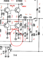
Look at the circuit...
There is a 500 ohm shown as being in parallel with the thermistor and its series 200 ohm. First thing is to confirm the values are what the circuit says because this is the kind of thing that can get changed in production. So make sure its as we see it on the diagram.
To reduce the output stage current, we can reduce the value of the 500 ohm. If we reduce it to zero (a short) then the amp will operate with zero bias and you would hear crossover distortion. Its impossible to determine the value needed by calculation, you are going to have to experiment. One possibility is to tag a preset across the 500 ohm (so the 500 ohm stays in place) and tweak it to some more reasonable value. A 2k or 2k2 preset would be suitable.
You could then remove the preset and measure what value its set to, and then calculate the value of a new single resistor to replace the 500 ohm.
Assuming it is, lets put some numbers in.
15.9 and 95 mv gives 15.9 and 95 milliamps respectively. So you should find the side with the highest current is the one running hottest. 95ma sounds a bit high, although you have to remember that the basic amp doesn't have this as an adjustable quantity, the exact value being determined by the actual characteristics of the individual semiconductors used.
We can reduce the 95ma to be something closer to the other channel but you have to remember that this amp has no pretension to maintaining tight control over this quantity like more modern ones do. So yes, we can pull it down but don't expect it (or the other channel) to be super stable in holding the set value.
Look at the circuit...
There is a 500 ohm shown as being in parallel with the thermistor and its series 200 ohm. First thing is to confirm the values are what the circuit says because this is the kind of thing that can get changed in production. So make sure its as we see it on the diagram.
To reduce the output stage current, we can reduce the value of the 500 ohm. If we reduce it to zero (a short) then the amp will operate with zero bias and you would hear crossover distortion. Its impossible to determine the value needed by calculation, you are going to have to experiment. One possibility is to tag a preset across the 500 ohm (so the 500 ohm stays in place) and tweak it to some more reasonable value. A 2k or 2k2 preset would be suitable.
You could then remove the preset and measure what value its set to, and then calculate the value of a new single resistor to replace the 500 ohm.
- Status
- This old topic is closed. If you want to reopen this topic, contact a moderator using the "Report Post" button.
- Home
- Amplifiers
- Solid State
- Will increaseing coupling caps cause problems