Just attached them to my post. Go to the Advanced posting method, and below the text entry field you will see a button called Manage attachments. That will allow you to upload multiple attachments, which in my case are images. I size my images to 800x600. Incearca, o sa vezi ca merge. ")
Thanks, this is helpful. (Eu m-am retras putin aici dupa hartuielile de pe elforum, acolo sa vezi actiune... )
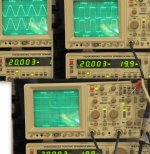
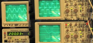
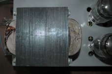
I've not seen yet much about a DIY interstage, so I attach a comparative test on a (same) 2x2 cm double C-core wound core as follows; Y1, upper on the scope, is an inverting 1:1, let's say, 10k:10k interstage transformer and Y2, lower position on scope, it's a bifilar wound bobbin having exactly the same wire and turns as the previous one (2x4800 turns, 0,08mm). In each of the primary windings there is a 22mA DC curent. Source impedance is ~2k (50+2k resistor), secondary load is a 10k resistor, test frequency 20kHz, 19.9Vpp.
)I've not seen yet much about a DIY interstage, so I attach a comparative test on a (same) 2x2 cm double C-core wound core as follows; Y1, upper on the scope, is an inverting 1:1, let's say, 10k:10k interstage transformer and Y2, lower position on scope, it's a bifilar wound bobbin having exactly the same wire and turns as the previous one (2x4800 turns, 0,08mm). In each of the primary windings there is a 22mA DC curent. Source impedance is ~2k (50+2k resistor), secondary load is a 10k resistor, test frequency 20kHz, 19.9Vpp.
Attachments
Last edited:
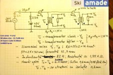
Hy Tyimo, I've mentioned in the sketchy drawing that the insulation is 0,1mm (with a secret touch) in both cases (though, not a reason to learn Romanian language). This is an "internal" test, I wonder why I put it here ☺...
I wait for BudP's, Yves's and (many)Somebody's opinion before saying that interstage are not good for coupling... I recall such a statement right in this post ... cheer up! go on, challange me!... it's springtime!
Best regards,
Dorin
I wait for BudP's, Yves's and (many)Somebody's opinion before saying that interstage are not good for coupling... I recall such a statement right in this post ... cheer up! go on, challange me!... it's springtime!
Best regards,
Dorin
Last edited:
Tyimo hi,
Overvoltage is not my concern, you can choose anytime higher insulation grade for the copper wire; I believe there are 3-4 classes of insulation (depending on continent, no kidding). No, the insulation is for dealing with capacitance inter-layers and for having a smooth and firm surface for tight winding.
I don't know what's "transposed bifilar winding", but this doesn't mean I didn't use it. The bifilar bobbin is wound very near to "normal", with a gentle personal touch. The inverting bobbin, for A2 dreamers, it's other league, very personal method, but let's say it's more like classical...
Dorin
Overvoltage is not my concern, you can choose anytime higher insulation grade for the copper wire; I believe there are 3-4 classes of insulation (depending on continent, no kidding). No, the insulation is for dealing with capacitance inter-layers and for having a smooth and firm surface for tight winding.
I don't know what's "transposed bifilar winding", but this doesn't mean I didn't use it
. The bifilar bobbin is wound very near to "normal", with a gentle personal touch. The inverting bobbin, for A2 dreamers, it's other league, very personal method, but let's say it's more like classical...Dorin
Last edited:
Actually (or funny enough) the cores were rejected 30 years ago by quality control for not having the physical dimensions in a given range. A wise engineer put the cores aside, about 50 pieces, and he gave the whole bunch to me last year, when the comparativ test was conducted.
Dorin
PS. I see that for the small winding machine the seller does not longer offer the economy shipping, shame on them! I remember that the shipp9ing was ~45 Euro about 2-3 years ago when I bought the machine.
Dorin
PS. I see that for the small winding machine the seller does not longer offer the economy shipping, shame on them! I remember that the shipp9ing was ~45 Euro about 2-3 years ago when I bought the machine.
Last edited:
HI Dorin!
Thanks!
"Transposing the winding is a technique that winds two wires A & B, such that they are in a configuration ABBAABBAABB rather than the normal ABABABABAB"
You can read about it here: http://www.diyaudio.com/forums/tube...windings-excess-1000-volts-3.html#post2462543
Greets:
Tyimo
Thanks!
"Transposing the winding is a technique that winds two wires A & B, such that they are in a configuration ABBAABBAABB rather than the normal ABABABABAB"
You can read about it here: http://www.diyaudio.com/forums/tube...windings-excess-1000-volts-3.html#post2462543
Greets:
Tyimo
For those of you who utilize E/I core you must use either the winding layout from the 30's RCA PA amplifier, and all of the early and famous Fender and Marshall guitar amplifiers, or you must use the following scheme.
Primary A1 #28
Secondary 4 ohm
Primary A2 #28
econdary 8 & 16 ohm
Primary B1 #28
Secondary 4 ohm
Primary B2 #27
The primaries are split (A1 / A2) at the CT, so, series connected, and each set has the full primary turns. Set A and set B are parallel connected outside of the winding. Doing this, along with the 75% to 85% build rule, will always provide overall DCR balance within 1 ohm, usually withion 0.05 ohm. The RCA PA winding scheme is the first scheme shown in the RDH4 section on OPT winding, and it is criminal not to have this reference, and will provide exact DCR balance, but is really not acceptable for modern audio reproduction.
Hi Bud,
pardon me for digging out this older statement of yours!
I don't see the benefits of this winding arrangement compared to another one with the primaries divided into four parts and arranged as follows:
primary A1
secondary 4 ohms
primary B2
secondary 8 and 16 ohms
primary B1
secondary 4 ohms
primary A2
The primary sections are connected in series this way: Plate terminal 1-A1-A2-center tap-B2-B1-plate terminal 2.
For Marshall OTs: Some 30 years ago I examined the OTs of a JCM 800 Super Lead and a Super Bass head respectively. They apparently were identical and wound this way:
secondary 1: 16 ohms
primary 1
primary 2
secondary 2: 4, 8 and 16 ohms
Primary 1 and 2 were connected in series with the center tap in between, secondary 1 was connected in parallel to the common and 16 ohms terminal of secondary 2.
Maybe your winding pattern was applicable to Partridge OTs as used by Hiwatt?
Best regards!
I have wound a few drivers and outputs. Output I use 13 windings. 7 secondaries quadrafilar for 4-9-16 ohms, can be done easier if only wound for 8 ohms. Most were 3 layers for each winding, and a lot of insulation. Wound by hand for almost 98 % fill. No fancy cores, just recycled scrap ones. -3db 7 cycles to 50Kc for this one.
S-1
A-3
S-2
B-1
S-3
A-2
S-4
B-2
S-5
A-1
S-6
B-3
S-7
http://home.roadrunner.com/~t7/
S-1
A-3
S-2
B-1
S-3
A-2
S-4
B-2
S-5
A-1
S-6
B-3
S-7
http://home.roadrunner.com/~t7/
Attachments
Hi fooeywuffle,
your winding pattern seems to be basically similar to mine (#195), but, of course, in a much more elaborate and sophisticated fashion. Great!
The conclusion of your tetrafilar secodary winding is that you parallel one wire of each of the seven segments, i.a. seven wires in parallel, leading to four 1 ohm packets, and arrange these to get those three impedances, isn't it?
- Status
- This old topic is closed. If you want to reopen this topic, contact a moderator using the "Report Post" button.
- Home
- Amplifiers
- Tubes / Valves
- Who makes their own OPT around here?