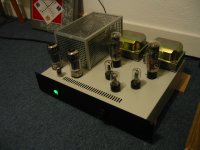
The outputs are for triode push-pull stage. All of them I have made are on my website.
T.E.C. TRIODE AMPS
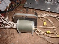
This one center leg is 2 1/2 inch by 4 inch.
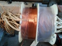
Wire size is picked so the ends of the winding comes out 1/8 inch from side of form, so it is probably larger than really needed.
Yes, 4 one ohm, 2 in series so 3 terminals twice, so can connect as 4, 9, or 16 ohm.
__________________
If brute force doesn't work, you aren't using enough of it!
T.E.C. TRIODE AMPS
This one center leg is 2 1/2 inch by 4 inch.
Wire size is picked so the ends of the winding comes out 1/8 inch from side of form, so it is probably larger than really needed.
Yes, 4 one ohm, 2 in series so 3 terminals twice, so can connect as 4, 9, or 16 ohm.
__________________
If brute force doesn't work, you aren't using enough of it!
A few things you need to do here.
1. Place a piece of electrical grade film tape between each crossover wire on the outside of your coil and the edges of the inter-layer papers. This will guarantee that you do not have a "surprise" waiting for you some day in the future. Seriously, you would be fired from my company for not doing this just because there is no way to guarantee that the high voltage wires are never going to move. Transformers swell and contract, measurably, as they go about their work, even audio transformers. I would prefer you remain alive.
2. Consider applying an air dry varnish to at least the coil. AC Dolph makes a very good material AC 41, that will provide and excellent barrier against additional oxygen arriving to fuel the corona death of your winding wire in the primary. A full dip is best, but even just drizzling it into the coil paper edges will help. I would not suggest you decide to use wax and a fry tank in place of this smelly for a week process.
3. Use less force and more taps to square up your core. put bolts in, finger tighten the kep nuts, lay a finger across the lams to help with resonances opening up the gap, and tap lightly. You will get a better closure of gap and you will not risk shorting from lam to lam due to bending the edge burr over and into an adjacent oxide protection on an adjacent lamination. Even a little shorting will mess up your audible character. Do not hesitate to use a thin cyanocrylate glue to insure the lams stay in their place. Just run a bead down each set of gap openings.
Otherwise, keep winding and learning, these things are fascinating.....
Bud
Primary A1 #28
Secondary 4 ohm
Primary A2 #28
Secondary 8 & 16 ohm
Primary B1 #28
Secondary 4 ohm
Primary B2 #27
The primaries are split (A1 / A2) at the CT, so, series connected, and each set has the full primary turns. Set A and set B are parallel connected outside of the winding. Doing this, along with the 75% to 85% build rule, will always provide overall DCR balance within 1 ohm, usually withion 0.05 ohm. The RCA PA winding scheme is the first scheme shown in the RDH4 section on OPT winding, and it is criminal not to have this reference, and will provide exact DCR balance, but is really not acceptable for modern audio reproduction.
Bud
Some more thoughts on this winding scheme:
It is believable that nearly, if not to say totally, DC resistance balance can be achieved by using thicker wire for the outermost winding section.
But: Under service, especially under full load, the transformer inevitably will get warm. It's interior winding parts will get even warmer that the exterior ones, and this even more, as for the innermost winding part the wire is thinner than for the outermost, which means that current densitiy for the innermost winding ist higher than for the outermost. Thus I strongly believe that perfect DC balance is achievable for a certain temperature only.
Now let's do some tweaking: After having completely finished the secondary 8 & 16 ohm part, we flip the bobbin, wind the other primary sections the other way round and connect the primaries as follows:
Primary A1
Secondary 1
Primary A2
Secondary 2
Primary B2
Secondary 3
Primray B1
I.e. Primary A1 and A2 are connected in parallel with Primary B1 and B2 respectively. All primaries use the same wire gauge. Could we agree upon that average DC resistance and average temperatures now are the same for both primary halves? So I think this winding pattern will provide good DC resistance balance over a wide, not to say for the whole usable temperature range.
But: Let's imagine what we're really talking about: DC resistance imbalance is about very few ohms, 100 ohms at the most I think, which is series connected to the primary load impedance and the plate resistances of both output tubes, all in the kOhm range. So what does it matter at all?
I think the real benefits of using a split bobbin (or two bobbins for CC cores) is good symmetry fo winding capacitance and stray inductance. Especially the latter is most important for all non truly class A desings, i.e. class AB or class B, 'cause stray inductances are switched on and off when the tubes start and cease conduction, which causes additional distortions if they differ too much.
Best regards!
Number of points here Kay.
What you propose is fine. It is even better if you cross connect the primary sectors in an X fashion. Distributed capacitance drops like a stone then. Just do not do it with other than commercial steel (M series) core material as frequency response peaks will be the result. Commercial core ceases to affect anything but rise time above ~500 Hz and direct antenna events take over from there, including shadowing etc.
The only reason I choose to drive both sides of a secondary is because of field linearity at the dielectric barriers and across the depth of the secondary winding. There are plenty of examples of doing it in the opposite fashion in the RDH4.
As for ohmic heating issues, this is not really a concern. Temperature rise within a coil is not more than 5 degrees C different for a typical coil from "Hot Spot" out to within 1/64 of an inch of the coil surface, after heat saturation. In addition all winding wire of modern manufacture and minimum classification has an expected lifetime of 300,000 hours before failure due to heat related causes, at a constant temperature of 155 degrees C. This is de-rated by UL, CE and other safety testing agencies to 130 degrees C for insulation system purposes and to make sure that the testing being done does not take forever due to anomalous failures in the test sequences.
In addition the likelihood of a continuous output at maximum power in an audio output transformer, for the time required to actually fail a device due to temperatures above the life rating of the insulation, are slim indeed. Not impossible of course.
Bud
It is believable that nearly, if not to say totally, DC resistance balance can be achieved by using thicker wire for the outermost winding section.
i have done this, it is true....

Patrick Turner has a site with lots of advice on winding from the world of RDH4. He argues that really good bespoke transformers can't be found in Australia. For me, not being able to buy one would be the only reason for winding one, because it takes a whole lot of effort to get exactly right. Even sourcing genuine high quality GOSS of the right grade is likely to be a problem...how could you check it's quality?
education+diy
In the UK we're lucky to have the excellent Sowter, who will wind whatever you want for the same (quite high) price as a standard model, as long as it fits one of their fairly wide range of sizes. Heavy to post, but no more so than the materials would be.
Ian
education+diy
In the UK we're lucky to have the excellent Sowter, who will wind whatever you want for the same (quite high) price as a standard model, as long as it fits one of their fairly wide range of sizes. Heavy to post, but no more so than the materials would be.
Ian
Exactly that Tony. Kay's concern about temperature rise likely stems from the fact that as commercial designers our job is to remove every penny from any given set of requirements. Turns out that there is a single design for every combination of current, voltage and expected lifetime. And, this single design is smaller than other designs just a few percentage points on either side of exactly hitting the target.
Even in the world of audio. Take the Peerless SE OPT for 300B tubes. A very small transformer, 7/8 by 1 core tongue as I remember, though Mike from Magnequest could provide the truth. A very good performing transformer, a bit shy on Bass, but considering what was used for Bass drivers at the time it was designed, near perfect. To make a significant improvement in overall performance requires an analysis of load lines differing from WE's best power / distortion recommendations (turns out to be 4.545 kZ ohms by the way) and a jump to a 1.5 X 2 center leg size. You can get more Bass by just going up 1/8" in tongue width, but the cost jumps by a bigger percentage than the tongue width. And, cost was and still is KING, in the commercial world.
Bud.
btw, i have done several opt's already and temperature is barely warm to touch even after extended listening, so perhaps things are not so bad as one might think, unless maybe if the whole traffo assembly is potted....i have not yet done potted opt's....
another question for BudP, why M6? and not M2?......
another question for BudP, why M6? and not M2?......
As you go deeper into the M series they become harder to stamp reliably. The material for M3 is 0.009" or 0.006" thick. M6 is 0.014" thick. M2 is not available in E/I laminations from anyone I know of. You may not even be able to successfully coil it, cut it and polish it for a C core. This just because of how thin it would need to be to remain ductile enough to work with. M3 is very brittle, we use amber hammers on it rather than steel, just to avoid damage.
On the other hand I have never gone looking either, as M3 in E/I laminations suits my needs. I use 29 gauge M6 for my level 4 audio transformers, 26 gauge M19 for level 3 (highest level of pro audio OPT's, like a 70 volt distributed line step down) and lesser grades for levels 1 & 2. I do not usually even speak about these first three levels, even though all of our Guitar Amplifier OPT's come from them. For audio reproduction I have levels 4 to 6, but call them level one to three. Obviously, just to confuse my enemies and such.
Bud
Bud, are amorphous irons available in EI's or just C cores?
Amorphous ribbon is very thin, 0.02 - 0.03 mm. So amorphous cores are either wound C or toroid.
i also read about amorphous irons in distribution transformers, are they the same thickness as 0.02 - 0.03 mm?
I suspect yes. Molten ribbon have to be cooled at very high ratio (1 million degree at 1 sec if I remember correctly), so its impossible to make it thick.
BTW, why do you want to use EI? To make quasi-distributed air gap? That not necessary, with double C core you can use thin mylar film (e.g. Hostaphan) between halves to construct desired air gap.
Homebrew xfmrs
Hi Folks,
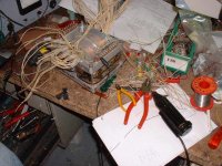
I´m late here. I had wound many transformers in the past. All wind by hand. Most of these are power or inverter trafos with low numbers of turns.
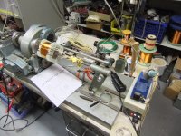
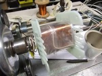
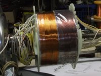
Since I came across with an old winding machine I wound opts and high voltage power trafos.
here some pics of my homebrew trafos:
upper row, left to right: homebrew MC-3500 opt, Coil former on winding machine, 400W opt for bass amp with 6 GU50, coil former of on the winding machine, ditto,
lower row: coil former nearly finished.
73
Wolfgang
Hi Folks,
I´m late here. I had wound many transformers in the past. All wind by hand. Most of these are power or inverter trafos with low numbers of turns.
Since I came across with an old winding machine I wound opts and high voltage power trafos.
here some pics of my homebrew trafos:
upper row, left to right: homebrew MC-3500 opt, Coil former on winding machine, 400W opt for bass amp with 6 GU50, coil former of on the winding machine, ditto,
lower row: coil former nearly finished.
73
Wolfgang
Attachments
- Status
- This old topic is closed. If you want to reopen this topic, contact a moderator using the "Report Post" button.
- Home
- Amplifiers
- Tubes / Valves
- Who makes their own OPT around here?